Thermaltake Dr.Power II ATX Power Supply Tester
 |
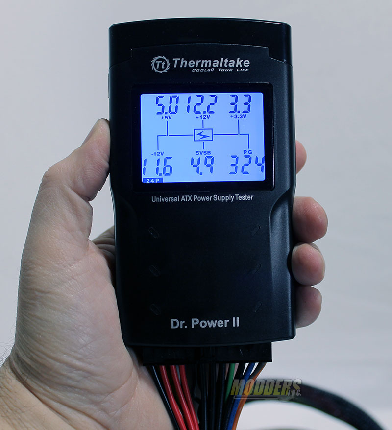 |
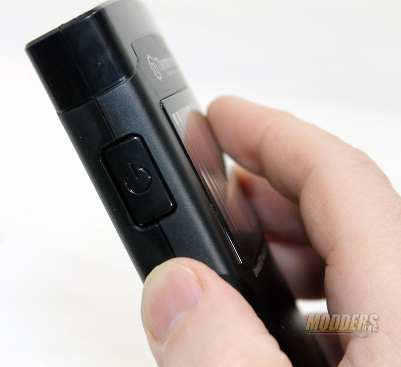
With the cables connected all you have to do is press the single button on the tester. The Dr.Power II tester has two modes, an automated mode and a manual mode. Once you have the cable connected to the test all you need to do is make sure that the power supply is plugged in and switched to the on position. Once the PSU is turned of the LCD will light up blue and will give you your first visual about the power supply.
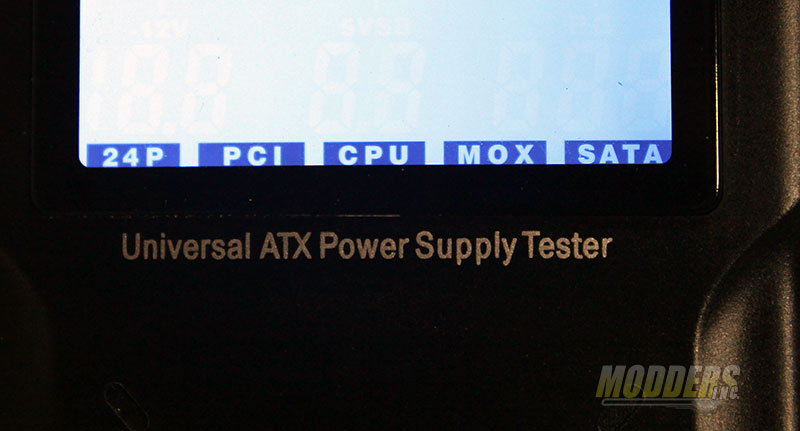 |
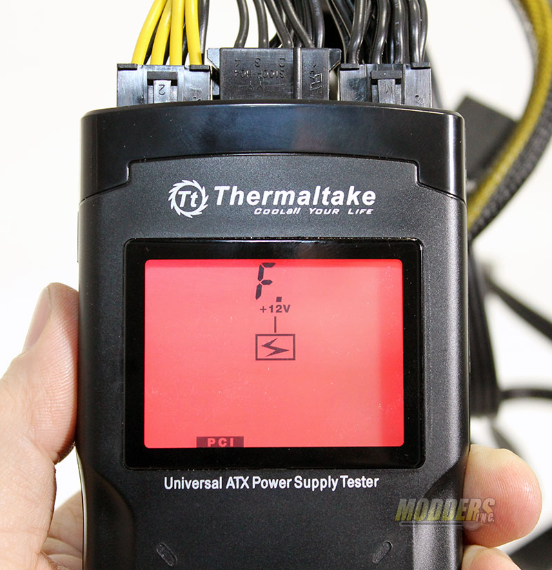
Once you have everything on and ready to go you will see at the bottom of the screen some tabs that show you which cables are plugged in to the Dr.Power II to be tested. As we can see you the display shows that the 24 pin, PCI, CPU, Molex, and SATA cables are plugged in and ready to be tested.
 |
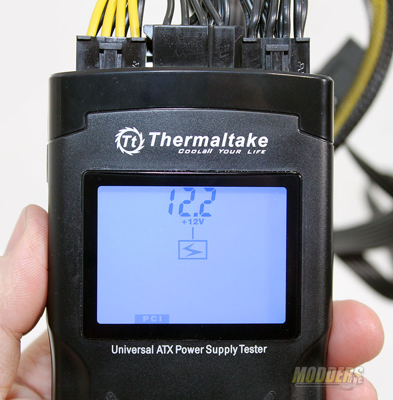 |
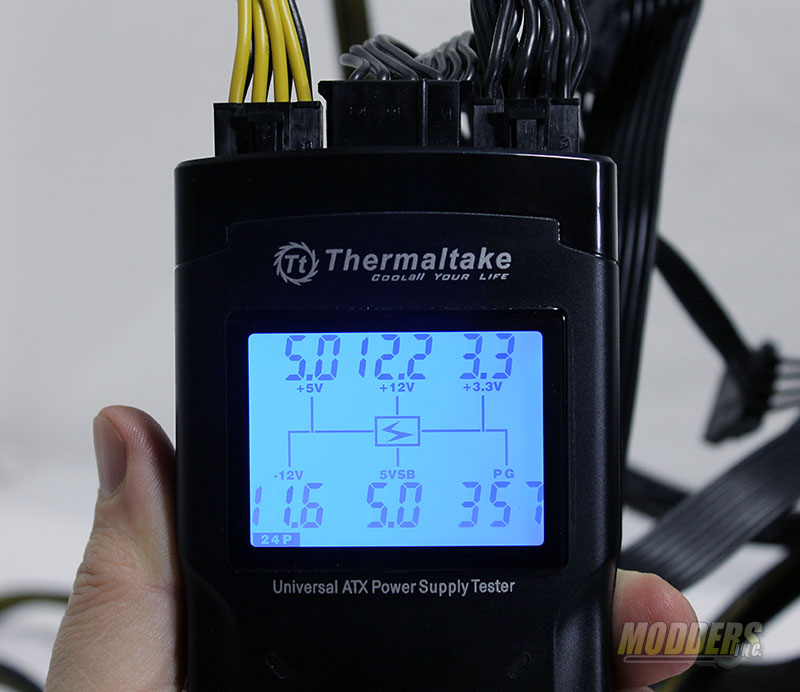
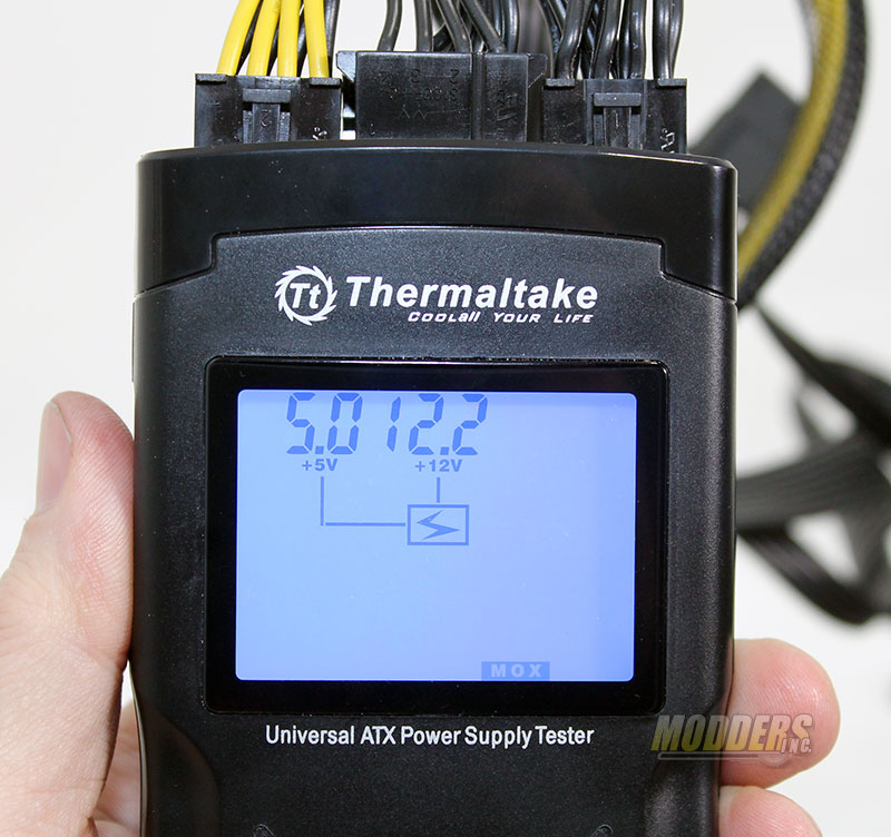
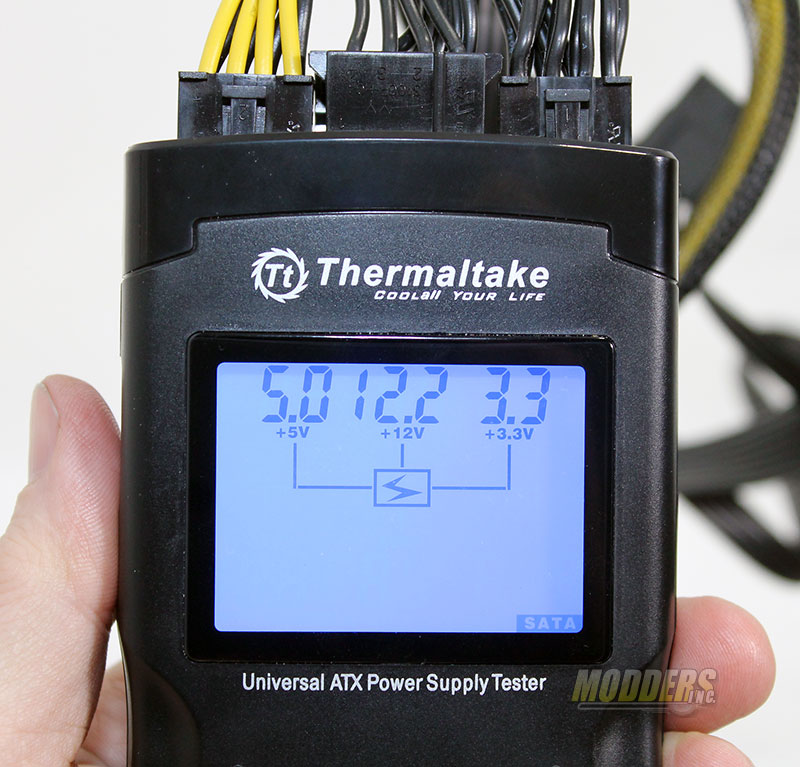
The tester has two testing modes (A and B) and they are very easy to use. With the unit ready to test you can start the Mode A testing. To start the Mode A testing you press on the Check Button (the button on the side) for LESS than five seconds. This will first display the the information at the 24 pin connector. Press the Check Button again and it will display the information about the next cable you have plugged in, press the button again and you get the next set of information and so on. Basically this the manual mode for the Dr.Power II tester.
 |
 |
The Mode B testing is an automatic way of testing. By pressing the Check Button MORE than five seconds it will go into the auto screen cycling. During the auto mode the test will display each screen for a period of five second before it goes to the next screen.
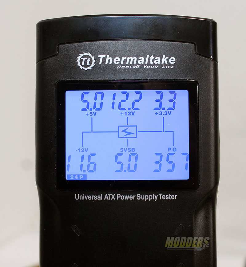
In case you have not noticed in the images the tester also displays the actually output of each of the areas check. This is also one of the things the Dr.Power II will test and give you a pass or fail on. The table below gives you the tolerance of each voltage allowed. This is a great reference chart to compare your power supply to the norm.
Output Specification
| Voltage | Intel Standard | Measure Range | ||
| Min. | Max. | Min. | Max. | |
| +5V | 4.75V | 5.25V | 4.6V | 5.5V |
| +3.3V | 3.1V | 3.5V | 3V | 3.6V |
| +12V | 11.4V | 12.6V | 11V | 13V |
| -12V | -10.8V | -13.2V | -10.5V | -13.4V |
| +5Vsb | 4.75V | 5.25V | 4.6V | 5.5V |
| P.G. | 100ms≦T≦500ms | |||
