Silverstone ML08 Case Review
Hardware Installation
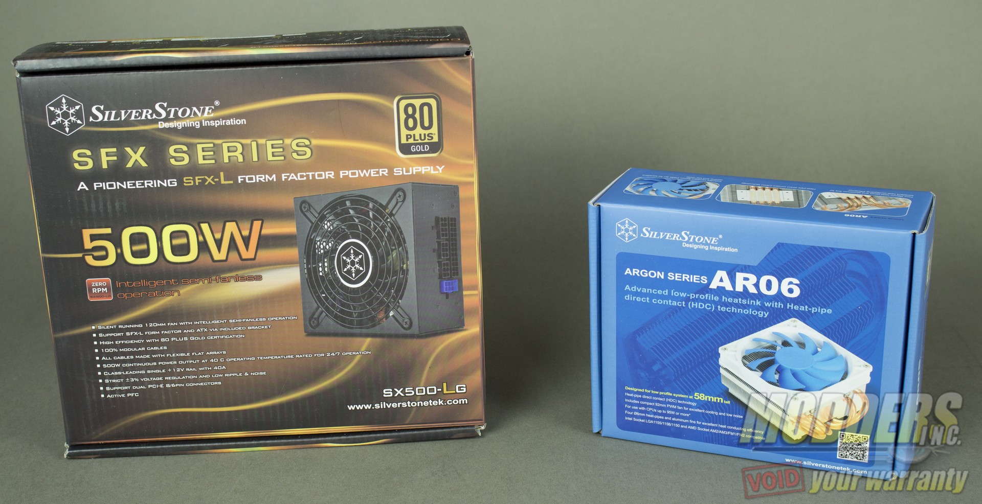
In addition to the ML08, Silverstone provided us with one of their SFX-L PSUs and one of their low profile CPU coolers. Why? Well, Silverstone has done a fantastic job of creating series of products that all compliment each other.
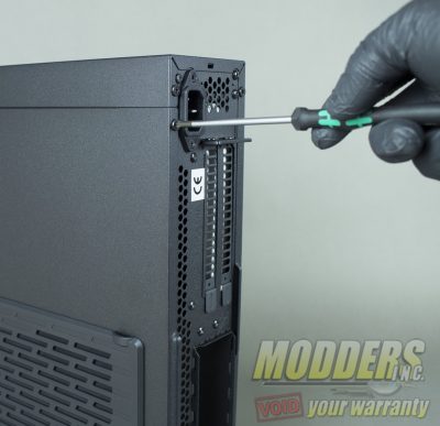
To begin installing components into the ML08, remove both side panels by removing three screws on each panels. Once the screws have been removed slide the panels up and pull away from the case.
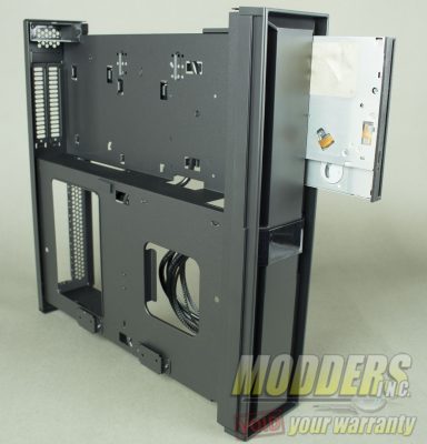
Next install the slim optical drive, this is not necessary as many users no longer use optical drives. Slide the optical drive in through the front of the chassis. To lock the optical drive in place, swivel the locking mechanism forward and slide the optical in place. Let the locking mechanism go and slide the optical drive back until you either feel the pins lock in place or hear an audible click.
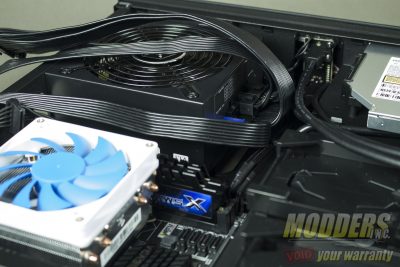
After installing the optical drive, install your SFX or SFX-L power supply, I would highly suggest installing your power cables first prior to fastening the power supply inside the chassis. The reason I recommend this is because for some users the space provided inside the cases might be to small to work in. Once the drive is locked into place, install the power supply retention bracket, this is not completely required but does offer stability from the power supply possibly shifting inside the case.
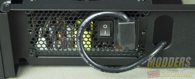
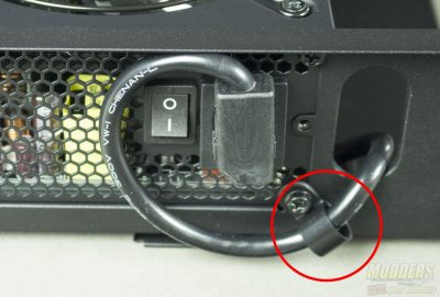
Once the PSU is installed take the PSU extension IEC plug and connect it to your PSU. I did find that the cable on the IEC plug does tend to be a bit suborn, so I recommend using a p-clip to help keep the cable from wandering off. At this time make sure your power supply is switched to the one position “|”, as once the panels are refastened to the case, you cannot access this switch from the outside.
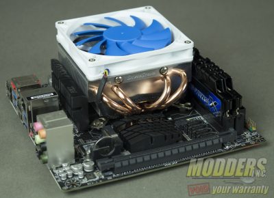
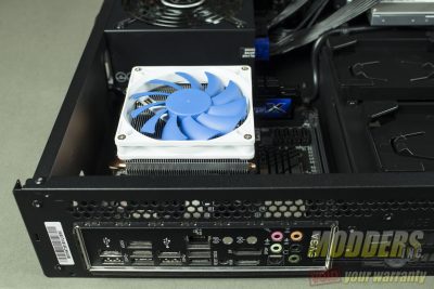
Up next, install the CPU cooler, in this case it is the Silverstone AR06 cooler. Be aware of the orientation of the CPU cooler as the heat pipes may block certain connectors on your motherboard.
*This step can be done after the motherboard is installed, due to the large opening on the back of the motherboard panel, but I found installing it outside the chassis much easier.
Next install the motherboard into the chassis, this will require four screws to secure to the standoffs. Once the motherboard is secure, run your 24pin and 8 pin cables to their respective connectors, the power supply has just enough clearance underneath it to hide excess cable clutter as well.
To help with cable management in this case, route your front panel cables below the power supply cables, and install them to the motherboard’s front panel header. I did notice that the blue LED did not illuminate, this was corrected after I flipped the LED cable around. Users should take note of this as many cases, the orientation of the front panel connectors.
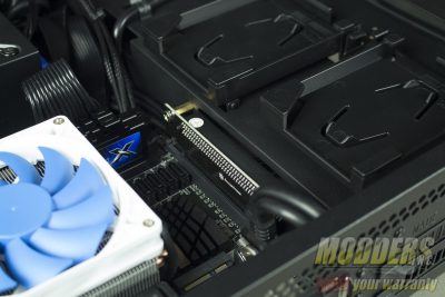
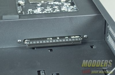
This next step is not required but I found it greatly helped reduce cable clutter. Prior to installing the 90 degree PCIe riser card, run your SATA power, USB 3.0 and audio cable beneath the slot on the mid panel where PCIe riser card is installed. Run your cables to their respective ports and once the cables are secure, install the riser card, you will need to fasten the card to the mid panel on the opposite side using two screws.
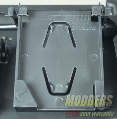
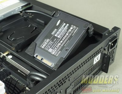
Before moving to the opposite panel, install your 2.5″ drives, the sleds come labeled and make sure the SATA power and data line up with the opening on the sleds which should point towards the inside of the chassis. Once the 2.5″ drive has been installed, lower the drive and clip the sled to the frame of the case.
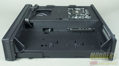
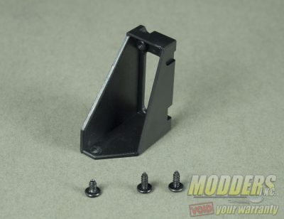
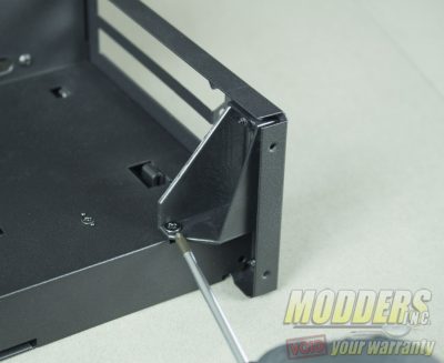
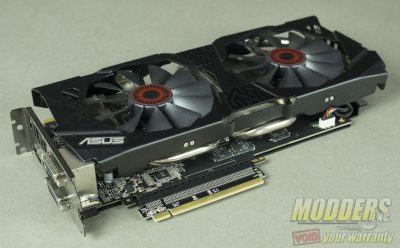
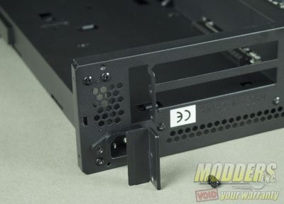
Once the optical drive, motherboard, power supply and 2.5″ drives are installed, flip the chassis over, this is where you can install either a graphics card or additional storage. For users that to install a high end graphics card that physically larger than than their reference model counter parts, you will need to remove this small bracket from the rear corner of the chassis.
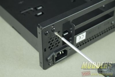
Remove two screws from the rear of the case and one screw that locks to the mid panel of the chassis to remove the bracket. It should be noted that once the larger graphics card is installed this bracket will no longer meet clearance inside the case. I also found that the GPU bracket support slider that was included with the accessories did not work with the larger cards as they block the mounting holes.
I do recommend attaching the 180 degree PCIe riser card to the video card first. I found it difficult to lock the graphics card to the 180 degree riser card, when the 180 degree riser card was installed to the 90 degree riser card first. To install the graphics card, first remove two screws from the PCI locking bracket. Once the card is installed and fitted properly, reinstall the PCI locking bracket and secure it with the two screws that were removed earlier.
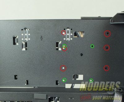
For those planning on additional storage, this option is still available with use of an accompanying graphics card that is under 6.7″ and allows for an extra 2.5″ or 3.5″ drive. The red circled areas are for mounting a 3.5″ drive and the green are for an additional 2.5″ drive. To the left of the additional drive mounting holes are the locations for the adjustable PCIe support bracket. For cards larger than reference design (MSI lightning/EVGA KP/Classified/ASUS Strix) this bracket cannot be used.
At this time I would suggest doing a quick post test, due to the layout of the components, troubleshooting may prove tedious when having to remove the external panels and handle. Once your system has successfully posted, slide and fasten both panels to the case.
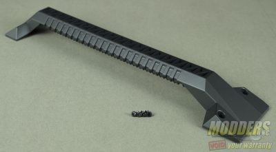
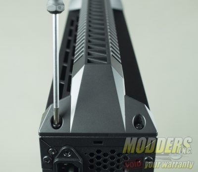
The ML08-H can be mounted vertically or horizontally, if you plan on using this was a HTPC, apply the four provided rubber feet to the bottom panel to prevent scratching. If you plan on using this as a mobile LAN rig, the provided handle can be attached via four included screws. The handle does not attach to the outer panels, but is securely mounted to the internal chassis. Once the handle has been mounted, any give that was found in the handle before is greatly reduced. One of the concerns I do have with the handle is that over time the exhaust from the graphics card may weaken the plastic material.
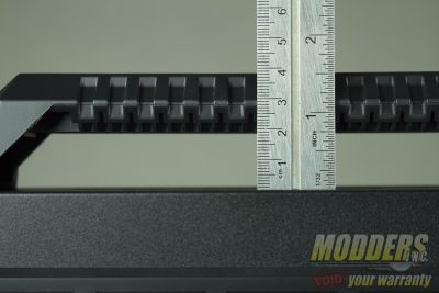
The handle provides 19 millimeters which for those with larger hands may prove cumbersome to use. I myself had this issue where my knuckle would hit the top of the case. This is not to say the handle is not useful, this is just something to be mindful of.
