Scythe Mugen 5 CPU Cooler Review
Installation of the Scythe Mugen 5
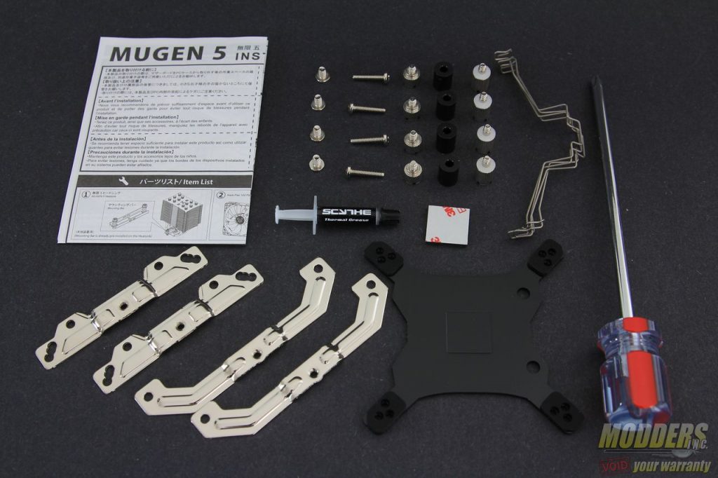
Everything required to install the Scythe Mugen 5 on an Intel system is provided in the bundle, including thermal interface material and screwdriver. AMD users will require the use of the stock backplate bundled with their AMD motherboard instead of the provided backplate.
For Intel systems, the backplate has three different positioned holes to accommodate LGA775, LGA1366 and LGA115x sockets. Because people have been asking, yes LGA115x covers every single socket including LGA1151, LGA1150 and LGA1156 because the mounting hole distance is exactly the same for all of those models.
The main idea is to basically secure the backplate with the stud nuts with the white plastic spacers/washers as buffer so the metal stud nuts do not scratch the motherboard surface on the front. There are two kinds of stud nuts provided, one is shorter and one set is longer. The shorter one is for LGA2011 sockets with the integrated locking mechanism. For LGA775 sockets, the provided square padding must be added at the center of the backplate first.
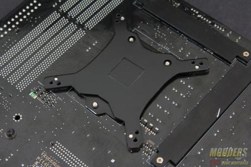
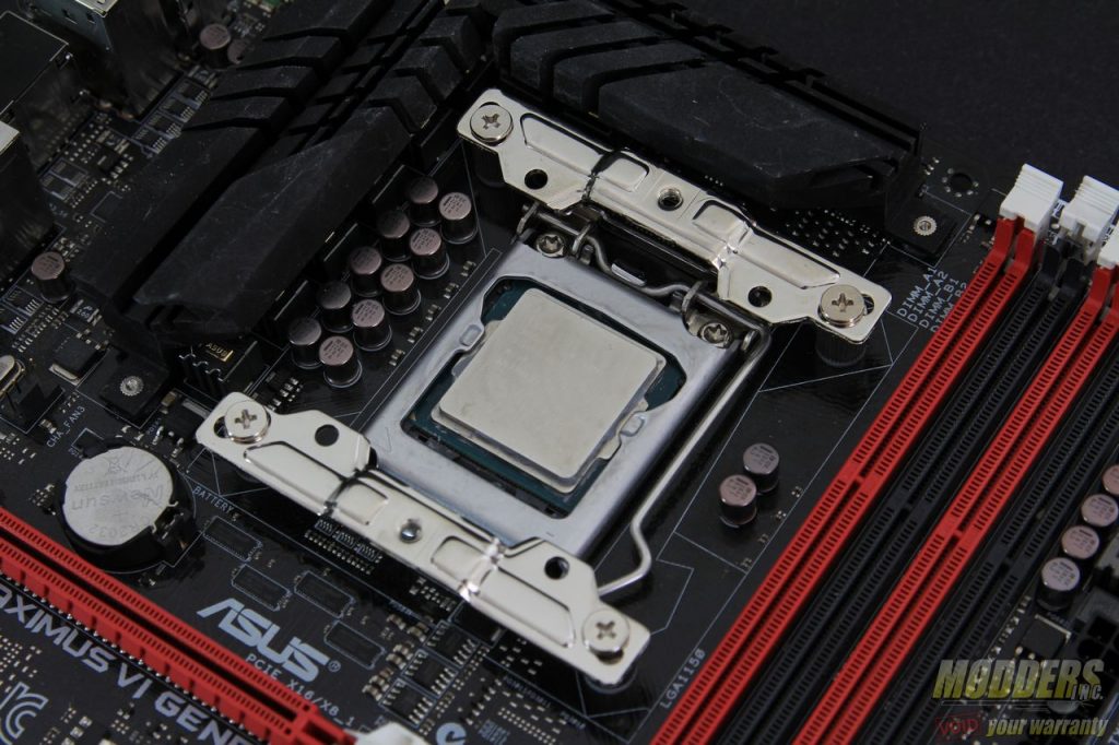
Position the backplate appropriately and take note of the position of the two holes at the top of the socket at the back of the motherboard. The tip edges of the backplate have padding that elevate the backplate and provide clearance for any surface mounted part close to the socket area. The stud nuts can be secured by hand or tightened by a screw driver. The pair of mounting plates install on top of these directly and secured with the four small flat screws provided. These mounting plates install with the curve facing inward and have three different mounting holes for LGA775, LGA115x and LGA1366 as well.
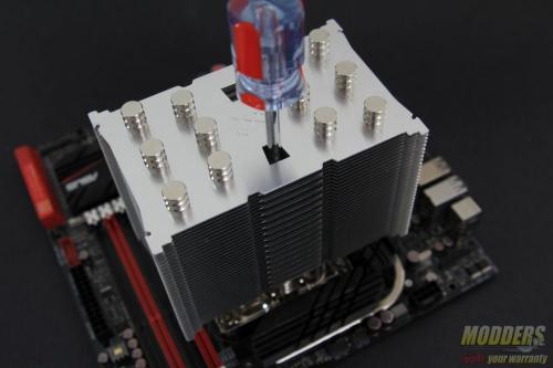
After the mounting bars are secured, apply thermal interface material on the CPU socket or on the heatsink contact surface (do not forget to remove the plastic cover first). Unlike previous Scythe CPU coolers the mounting bar is already pre-installed which saves a lot of time. There is a cut-out on the aluminum fin stack that allows for the screwdriver provided to pass-through and secure screws in place.
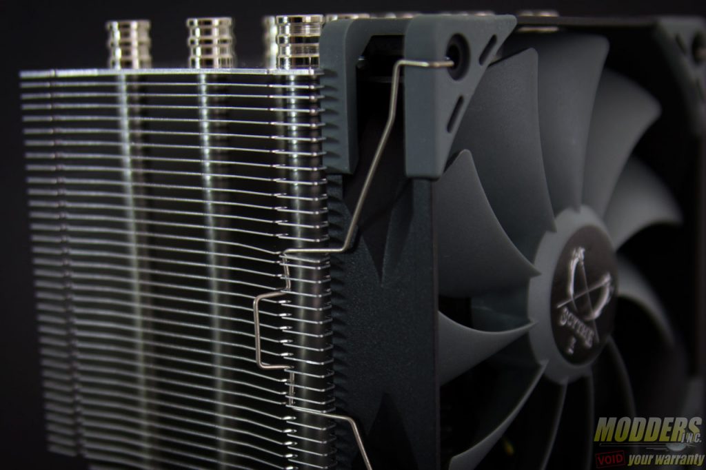
Always make sure to tighten each incrementally so that pressure is distributed across properly. The last step is of course installing the fan and it is fairly self explanatory since the fan clips just attach to the edges.The measurement for these fan clips are remarkably exact and contact is very tight without being difficult to remove or install.
Clearance Compatibility
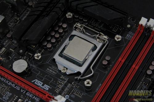
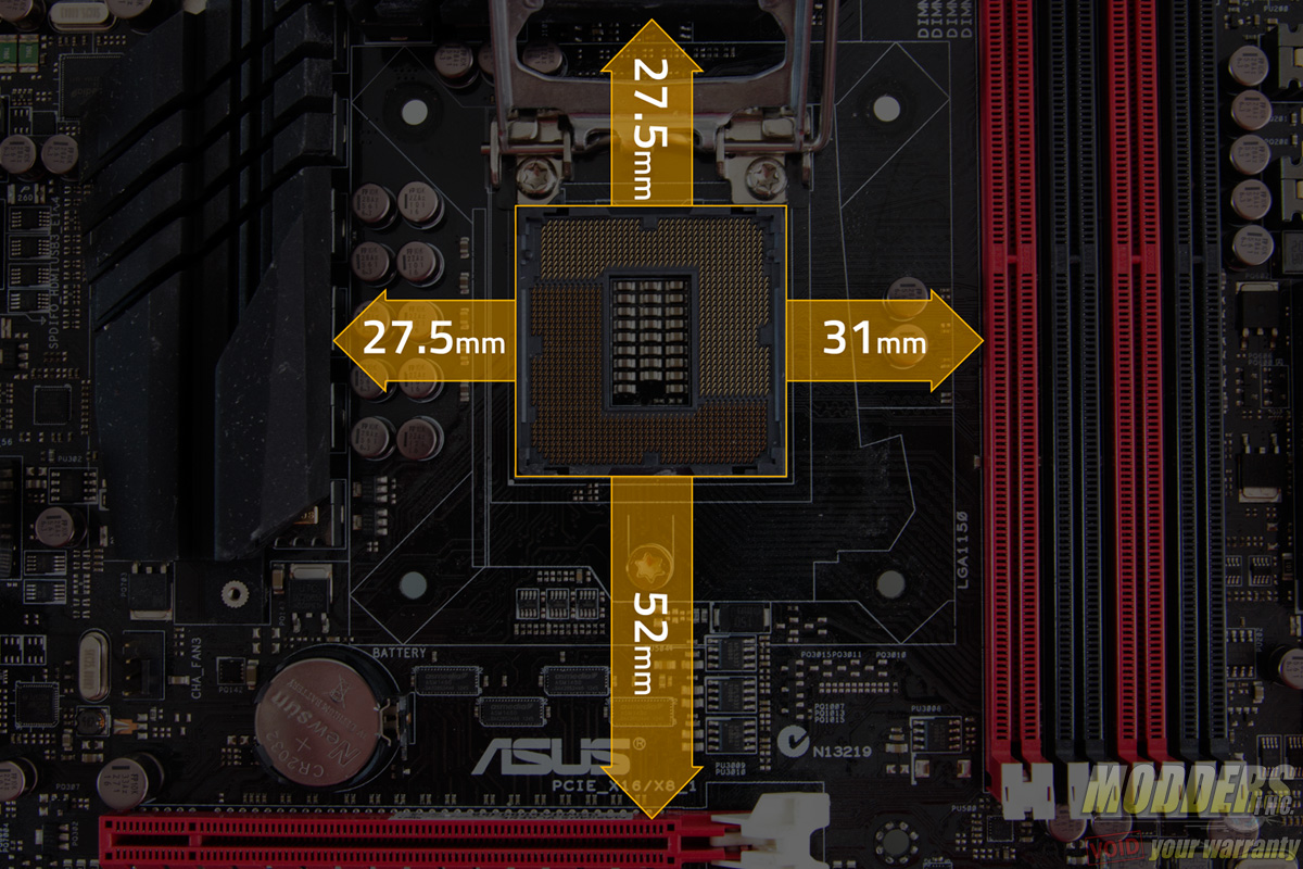
The test motherboard is an ASUS Maximus VI Gene micro-ATX motherboard and measuring from the edge of the socket (the gray plastic part), there is a 31mm gap between the CPU socket and the first DIMM slot as well as a 52mm clearance between the CPU socket and the topmost PCI-E x16 slot where the graphics card is installed.
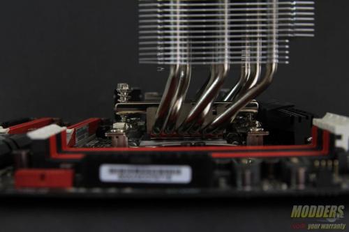
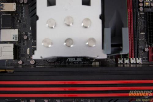
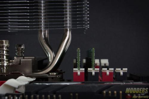
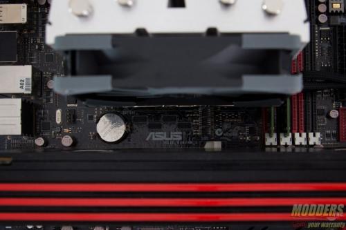
In the east/west orientation, DRAM poses no clearance issues because of the heatpipe offset allowing for extra clearance at the right even with a fan installed. As for PCI-E clearance, there is plenty of room between the side of the heatsink and a video card with a backplate as well.
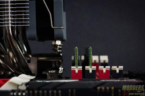
In a north/south orientation, the offset heatpipes allows for DRAM clearance cleanly. In the event that a north/south orientation is necessary but the VRM heatsink is on the way, there is still more than enough space underneath to fit a standard size DRAM module before it touches the heatpipe. For PCI-E graphics crards, the large space because of the offset heatpipes poses zero clearance issues with any video card currently in the market.
