Sapphire PURE Black X58 Intel Motherboard
A Closer Look – Components and Design |
Here we get our first fill look at the new motherboard from SAPPHIRE. They are taking the name, PURE Black, to the max with a full black motherboard, heatsinks and other misc items. We will be taking a spin around the board and while we are on our trip I will be highlighting the features of this new addition to the SAPPHIRE line. So let’s jump in…
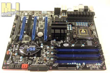 First off, in case you did not catch it before, the PURE Black X58 motherboard is an Intel board that supports the 1366 series of processors. The X58 in the name does of course mean that it uses the X58 and ICH10R chipset. Along the edge off the board that faces towards the front of the case is the 24pin power connector, one IDE, and 6 SATA connectors. 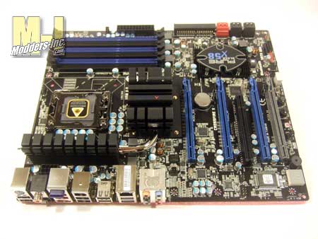
The output section of the board is jammed packed with stuff and which will go over in more detail later in the review.
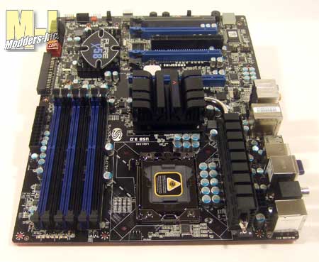 Here we can see that the 1336 CPU is surrounded on two side by the heat sinks and one side by the memory slots. The DDR3 modules slots are a good distance away and they should not get in the way of any aftermarket cooler even if you use some taller modules with cooling fins. 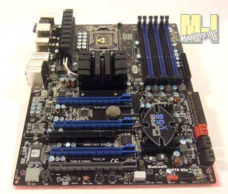
A hand full of PCIE slots are place on the board, more on that below.
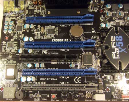 One, two, three, four PCIE! WHOA hold on there for a second those quad-ness thoughts you just had will have to stop. Go back and take a look and you will see that three of the four slot are the same color while the lower fourth one is gray. That is because it is a PCIE4_X4 PCI-E1.0 x16 slot while the other three are PCI-E2.0 and what I really like is that they are clearly labeled on the board what X they are; a 16x with two 8x. Also clearly labeled is the fact that this is a CrossFiresetup. I mean come on you know it was going to be, right. I personally would not see a AMD/ATI company buying the rights to use SLI. Right in between all this action is an single PCI slot. 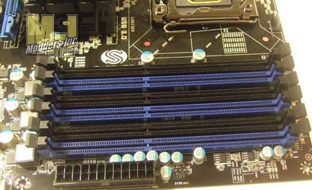 Yep, that is six 240 pin DDR3 sockets you are looking at. They can hold up to 24GB (6 x 4GB) of DDR3-1066/1333 DIMMS. That is quite a bit of you ask me and I would love to be able to fill that up to the max. You have to make sure that you do populate the right slots when you are installing your memory. The blue slot do need to be filled first and then you can go grab another set of triple channel memory and put them in the black ones. 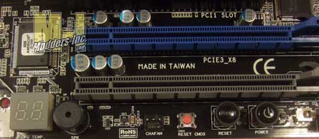 I realize that this is a small image but there is actually a lot going on here. Normally I would start from the left and go right when giving this tour, but today I feel like mixing it up so we will go right to left. The first button we encounter is and onboard on/off power button and his partner next to him is a reset button. Both of these buttons light up when the board is fully powered. Close but not to friendly, maybe because it is smaller, is the clear CMOS button. He can get you into trouble so maybe it is good that it sits away from the other two. Now you might be thinking why in the world would they be putting buttons on these? After all you have wires coming from the case to all this – minus the clear CMOS- so why the buttons. Overclocking… you see with these buttons you can do all the trial and error you want a fast pace and easy access. Locked up during boot? Hit the reset, still wont load? Clear the CMOS and stat over. They also allow you to have easy access to them in case you have to spend some time debugging the system. Next to the red button is one of six cooling fan pin outs located on the board. After a short walk we come to a PC speaker; got to hear those errors code beeps and stuff right. Now this is cool the “white cube” is a LED readout that you can use for debugging in case you do run into an issue. It also has a secondary job of displaying the CPU temperature after the system has fully booted… nice.
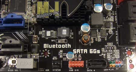 Well we might as well do like we did before and go right to left. This one will be a little quicker. The multi colored pin out is the front panel connection for the reset, power, and indicator lights. Next we have a SATA 2 connector, a USB header, system fan pin out, a IEEE1394a (firewire) connector – will this ever go away?- and a little itty bitty switch that could probably save your a%* one day, a BIOS switch… a what? The PURE Black X58 has two BIOS’es so if you mess the primary one up you have a secondary one to fall back upon and to get you going again. |
