Hardware Installation
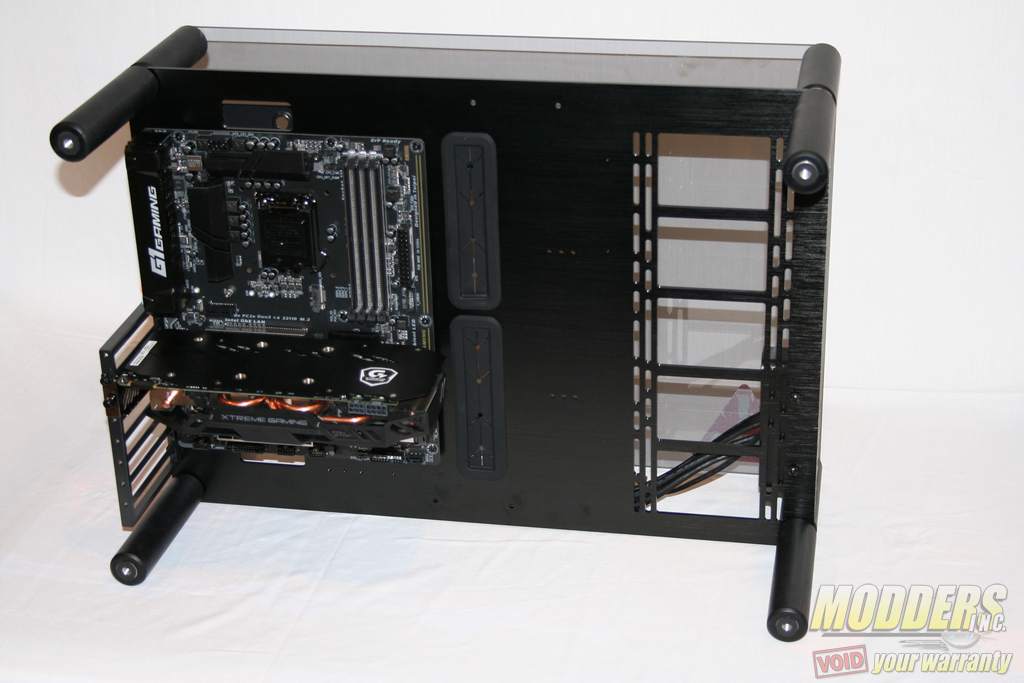
The PAEAN with an open-frame chassis it could not be easier to install the main computer components (i.e. motherboard, power supply, video cards, etc). There are no constricting exterior panels or tight spaces that must be dealt with. The main panel is easily accessible from all sides of the chassis. The only challenge would be cable management since every cable will be easily visible, with no panels or covers to hide anything.
Installing the motherboard is fairly straightforward. Simply screw in the 9 included motherboard standoffs in the designated areas identified in the instruction sheet. Once completed, the motherboard mounts onto them and is secured with the 9 included motherboard screws. With no rear panel you cannot use the motherboard’s rear cover plate since it has no where to be mounted.
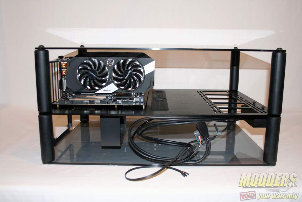
Installing a graphics card into the PAEAN is also simple. Just select which slot you want it on the motherboard and insert it. Use the supplied video card screws and secure it to the PCI bracket. Ensure that the rear video connectors are lined up correctly in the PCI bracket slot openings.
Video Card Clearance
With this open-frame case design there is no real limitation in the maximum length of the video card. The only limitations would be when other components would interfere with the video card. The specifications state that the maximum video card length is 310 mm, but that is only if a vertical reservoir is mounted to the right of the motherboard. The maximum length without a vertical reservoir (but with an installed radiator) is increased to 400 mm. There is about a 130 mm clearance from the top of the PCI slots to the tempered glass panels.
CPU Cooler Clearance
The specifications state that the maximum CPU cooler height is 140 mm. If the chassis is used in the bench table configuration with the top tempered glass panel removed, then this limitation would be eliminated as there would be no clearance issues. With the tempered glass panels installed, you are pretty much limited to low profile air CPU coolers if that is what you desire.
Due to the large distance between the CPU mount and the radiator mounting, the All-In-One liquid CPU coolers are not practical nor recommended. The distance from the middle of the CPU mount to the top of the radiator mounting is 400 mm. That measurement is on a straight line basis with no accounting for the bending of the tubing.
This case has been designed with custom water cooling setups in mind; with dedicated reservoir and radiator mounts built into the motherboard panel. Water cooled CPU water blocks would still be limited to the same 140 mm clearance, but that is mostly directed to the vertical fittings installed and the tubing bend radius.
PSU Installation
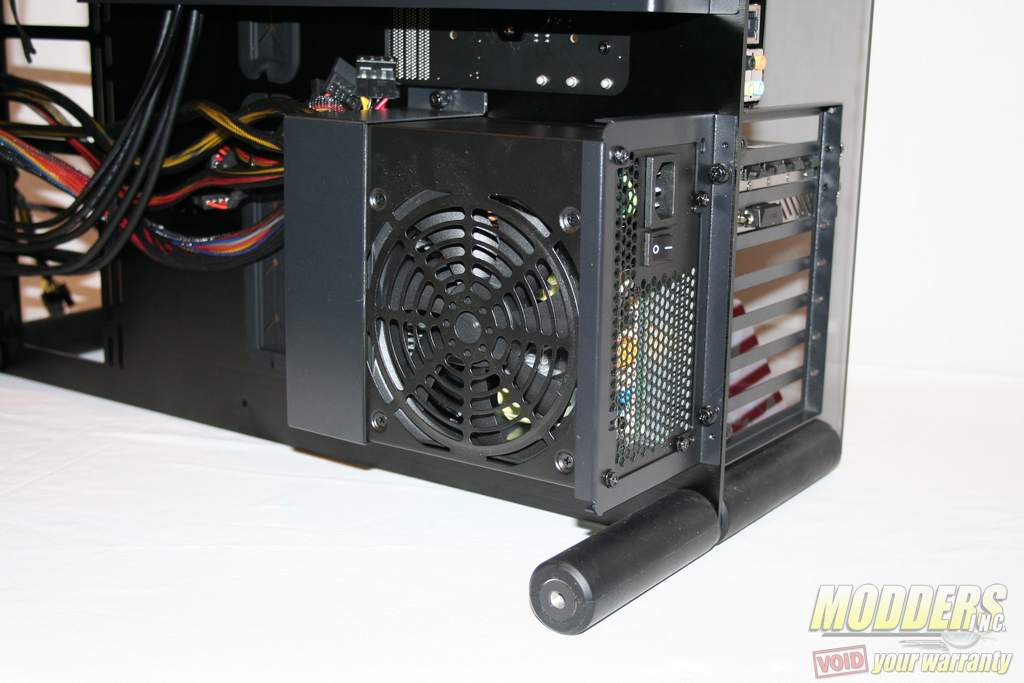
Mounting the power supply on the rear panel is easy since there are no case panels getting in the way or tight access panels to deal with. The PSU is mounted to the rear PSU bracket with normal screws and then secured in place with the front PSU bracket. The underside of the front PSU bracket has a rubber strip to help grip the PSU. The small parts box contains four rubber PSU anti-vibration pads that you can stick on the chassis frame to help cushion the PSU and prevent vibrations from affecting the chassis. It is recommended to have the PSU fan facing outward so that cool air can be drawn in easily.
I had a spare non-modular HEC-600TC-5WK 600W ATX PSU that was 140 mm in length and mounted it with no problems. A modular PSU would be preferred to reduce cable clutter since it is difficult to hide any unused cables on a open-air chassis.
Radiator Mounting
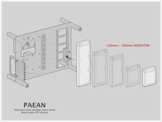
The chassis has an area specially created for radiators. This space can accommodate radiators in sizes of 120 mm, 140 mm, 240 mm, 280 mm and 360 mm.
3.5″ HDD Installation
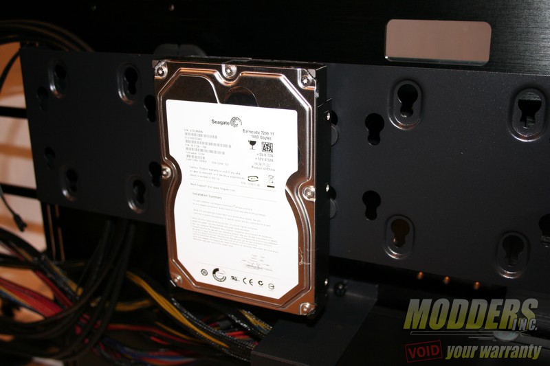
Mounting the larger 3.5″ drives is as easy as attaching four mounting screws to the underside of the drive and sliding it into position on the hard drive cage. With the connectors facing upward there is a 20 mm clearance between the bottom of the hard drive and PSU mounting area. With the connectors facing downward the clearance is increased to 40 mm. In this photo I mounted a Seagate 1TB hard drive in the connectors in the upward facing position. The 3.5″ hard drives mount onto the non-recessed holes of the hard drive cage.
2.5″ HDD Installation
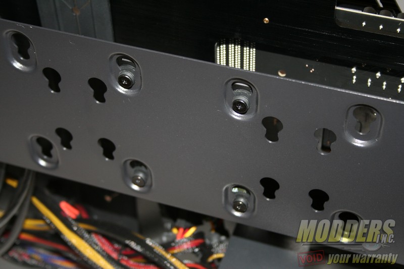
Mounting the 2.5″ drives are just as easy as the 3.5″ drives. Simply attach four mounting screws to the underside of the drive and slide it into position on the hard drive cage. The 2.5″ hard drives mount onto the back of the hard drive cage in the recessed holes. The holes are evenly spaced so there are five possible mounting positions for the drives, but only three may be mounted at any one time. These recessed mounting holes allow you to mount the 2.5″ drives without interfering with the front-mounted 3.5″ drives.
Cable Management
As with any open-frame chassis, cable management must be at the forefront during the planning and installation phases. The only place to hide any cables is directly behind the hard drive cage, but if all six hard drive positions are utilized then it will be extremely difficult to hide anything. Using a modular power supply will definitely help alleviate any unnecessary power cables from cluttering the build. The use of the supplied cable management clips will help immeasurably with organizing the cable clutter into a more polished result. Use the provided cable pass-through holes for routing the necessary cables in a logical and efficient manner.
