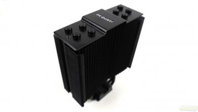
Be Quiet Dark Rock TF Review: Setting the Silent Cooling Standard
Installation of the BeQuiet Dark Rock TF
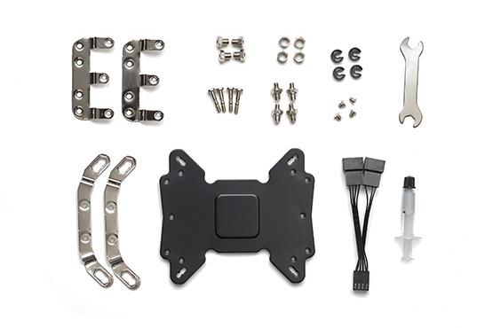
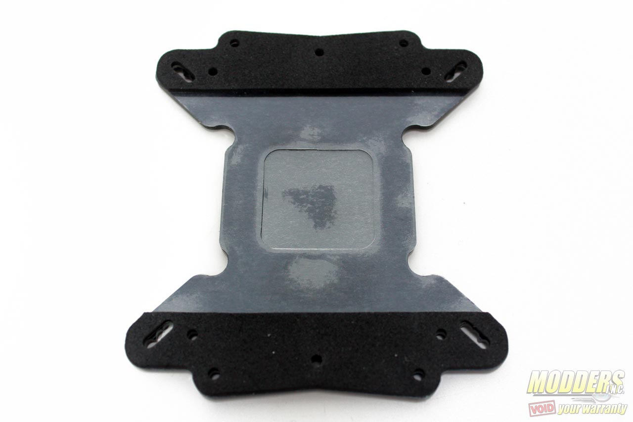
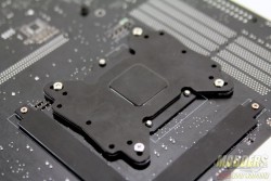
Before proceeding with installation, lay out all accessories and cross reference the package content with the illustrated user’s guide. With the exception of LGA2011 systems, the heatsink installation begins with the universal backplate where it must be deduced which hole the four M3x15 screws have to go through. If installing on an LGA 2011 system, you can skip all the parts that deal with securing the backplate and simply screw-on the LGA2011 spacer nuts on the motherboard integrated locking mechanism before proceeding directly onto the step below about securing the mounting plate. Obviously, the side of the backplate that is shielded and padded is the side that will touch the motherboard area. For AMD sockets 754, 939 and 940, the middle holes are utilized while current generation AMD AM2/3/FM1/FM2 uses the four holes at the very tips. Intel mainboards utilize the elongated mounting hole comprised of three sizes for LGA775, LGA115x and LGA1366 mainboards. LGA775 uses the closest square hole set while LGA1366 uses the most distant.
AMD Installation
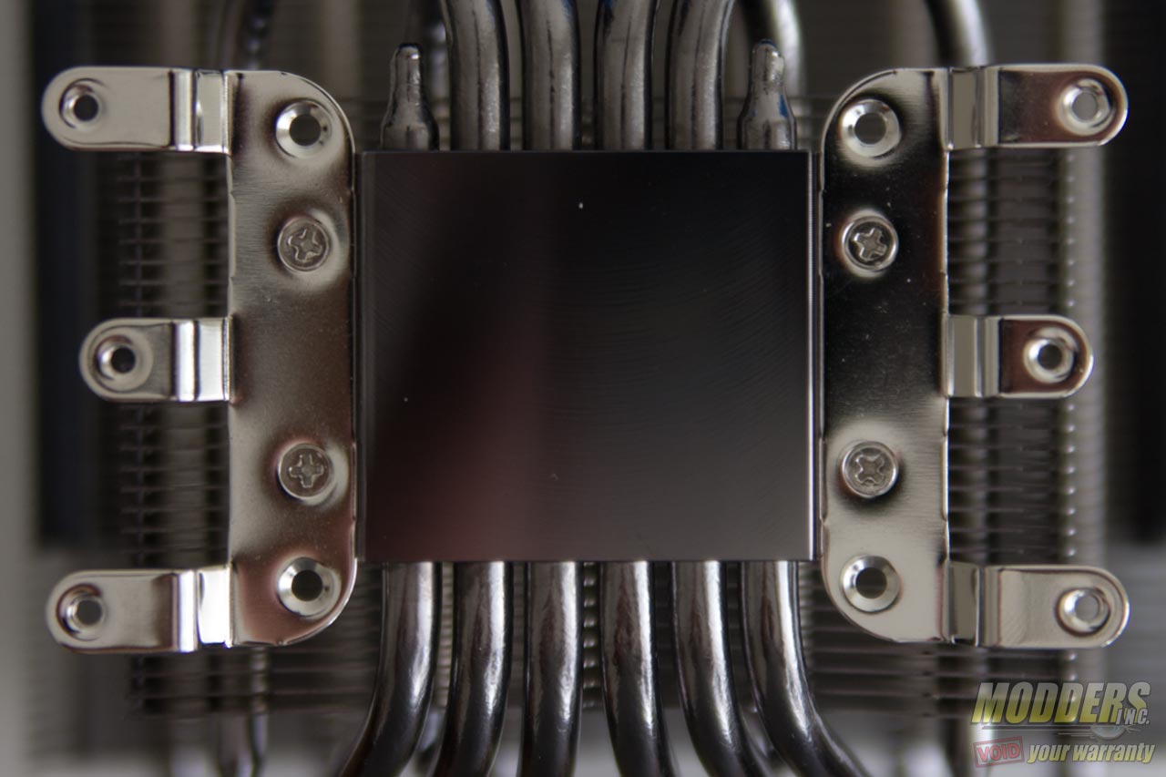
Place the M3x15 screws throught he backplate and position it to the board, then take the C-type profile spacers and secure the backplate before proceeding. This frees up one hand so the Dark Rock TF unit can be installed conveniently even when the motherboard is in a vertical position. The next part is to assemble the AMD mounting brackets to the base of the Dark Rock TF using a screw driver. After these two parts have been done, the user can apply thermal paste on the CPU or on the base of the heatsink and secure the Dark Rock TF onboard by screwing the M3x15 screws at the rear to tighten down the contact.
Intel Installation
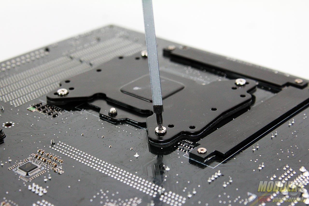
Unlike mounting the AMD system, the Intel backplate is positioned sideways, as if the backplate is a butterfly on the back of the mainboard. Since it is a very large backplate, some solder tips on this side of the mainboard will be touching the padded area but this should not be an issue. Some specialty or mini-ITX mainboards however may have a surface mounted capacitor that will be obscured in this area, so it is not advisable in that specific case to mount the Dark Rock TF due to the pressure that will be applied physically once the heatsink unit has been secured. After positioning the backplate and pushing through the M3x15 posts, secure them with the C-type spacers as well similar to the step in the AMD motherboard installation.
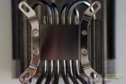
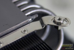
The Intel brackets are also secured with the small M3x3 screws at the base but the difference this time are the nuts that will have to go to the brackets. While it is possible to mount the heatsink with this step last and by using the spanner included, that is actually much more difficult than necessary. It is always much easier and much more secure to simply secure the contact by tightening the heatsink to the backplate assembly by twisting the M3x15 post screws at the back with a screw driver. As usual for Intel systems, depending on your motherboard’s size, there are three spaces to adjust the bolts to so that it matches with the post on the backplate. Tighten the two-piece hex nuts together to the desired position with the included spanner until it does not move anymore.
Apply thermal paste into the CPU IHS surface or on the heatsink surface, align the nut assembly to the M3x15 post screws of the backplate then tighten in a criss-cross fashion a few turns at a time so that the pressure spread is equal. This is easiest when done by placing the Dark Rock TF heatsink upside down on a table and placing the motherboard on top with the backplate facing the user so that the rear screws can be secured.
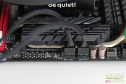
The fan installation is fairly straightforward as the wireclips hook through the corner holes and latch to the side of the Dark Rock TF. It is tight so it will take some effort to secure it and as for removal, it is advisable to light one corner hook first which is easier than removing from the middle. Make sure both fans installed are going to flow in the same direction then plug them into the motherboard fan header separately or via the splitter included in the accessory package.
Compatibility and Clearance Issues
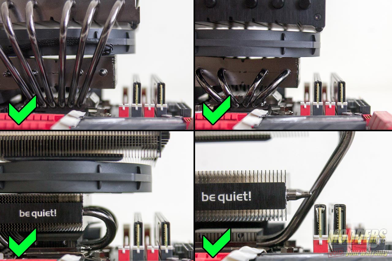
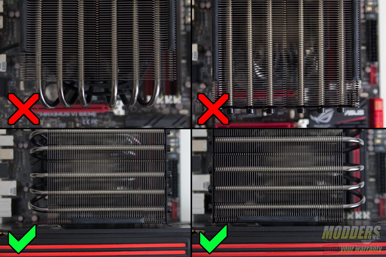
The Mushkin Stealth RAM used in this review measures 31.5mm tall in total from PCB base up to the top of the heatsink (standard DDR3 PCB measures 30mm tall). The test system motherboard is an ASUS Maximus VI Gene motherboard with a 28.5mm clearance between the CPU socket and the first DIMM slot and has a 45mm gap between the CPU socket and the topmost PCI-E x16 slot. The photos below show the clearance level provided for the RAM and PCI-E.
RAM Clearance:
PCI-E Clearance:
