MSI Z97 MPower MAX AC Motherboard Review
A Closer Look at the MSI Z97 MPower MAX AC Motherboard
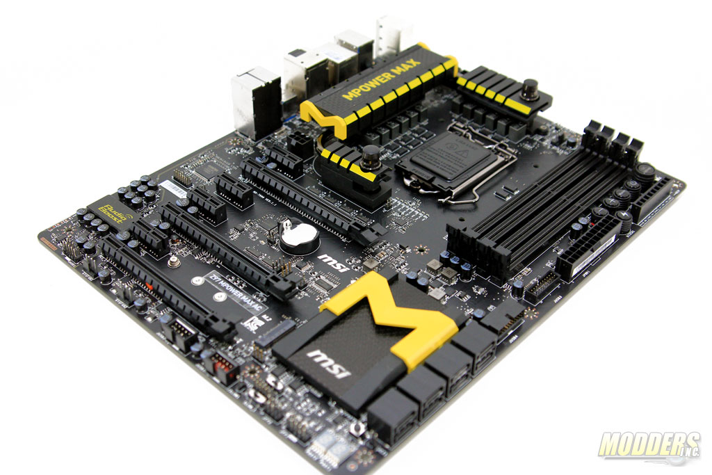
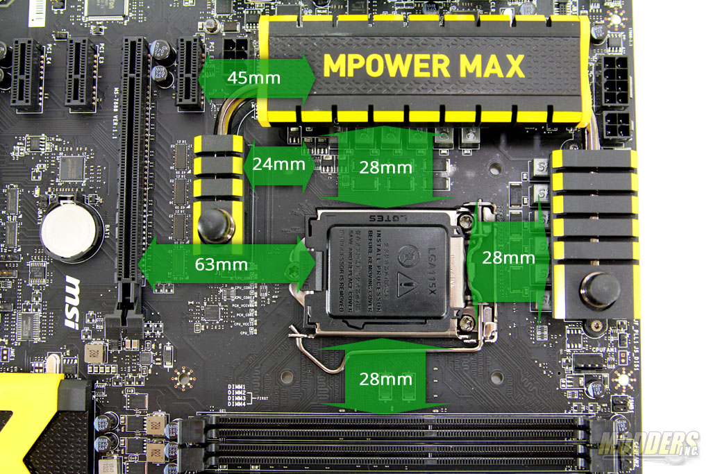
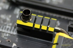
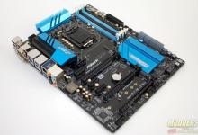
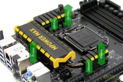
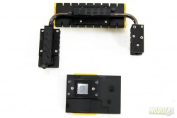
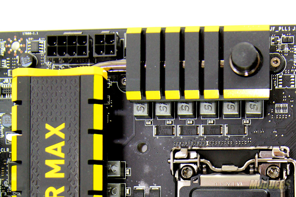
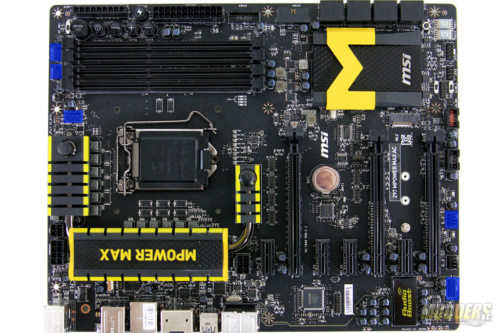
The packaging might be similar but the board layout itself has been redesigned on the new Z97 Mpower MAX. The standard form factor, 8-layer PCB motherboard measuring 305 x 244mm returns to an “air-flow” friendly heatsink design with a twist compared to the monolithic block of the Z87 MPower MAX. The new 3-piece VR heatsink hybrid design also doubles as a water-block with barbs readily available for water-cooling use.
The two largest pieces of the heatsink cover the CPU VR section with the smaller 3rd piece not directly cooling any component underneath. This heatsink assembly is secured to the board with six spring loaded screws. The Intel chipset heatsink on the other hand is smaller and simpler, albeit slicker looking cover compared to the larger and LED-lit MSI logo Z87 MPower MAX chipset heatsink.
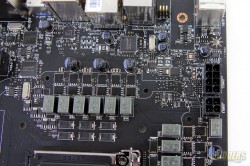
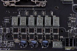
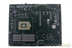
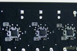
The power delivery design has also changed compared to the Z87 MPower MAX. Phase count is down from 20 to 12 utilizing a 6-phase Intersil ISL6388 VRD12.5 controller with six ISL6611A doublers at the back. ON-Semiconductor NTMFS4C08N (high-side) and NTMFS4C05N (low-side) Power MOSFETs are used instead of NXP PH7030AL/PH3830DL LF-PAKs that were used on the Z87 MPower MAX.
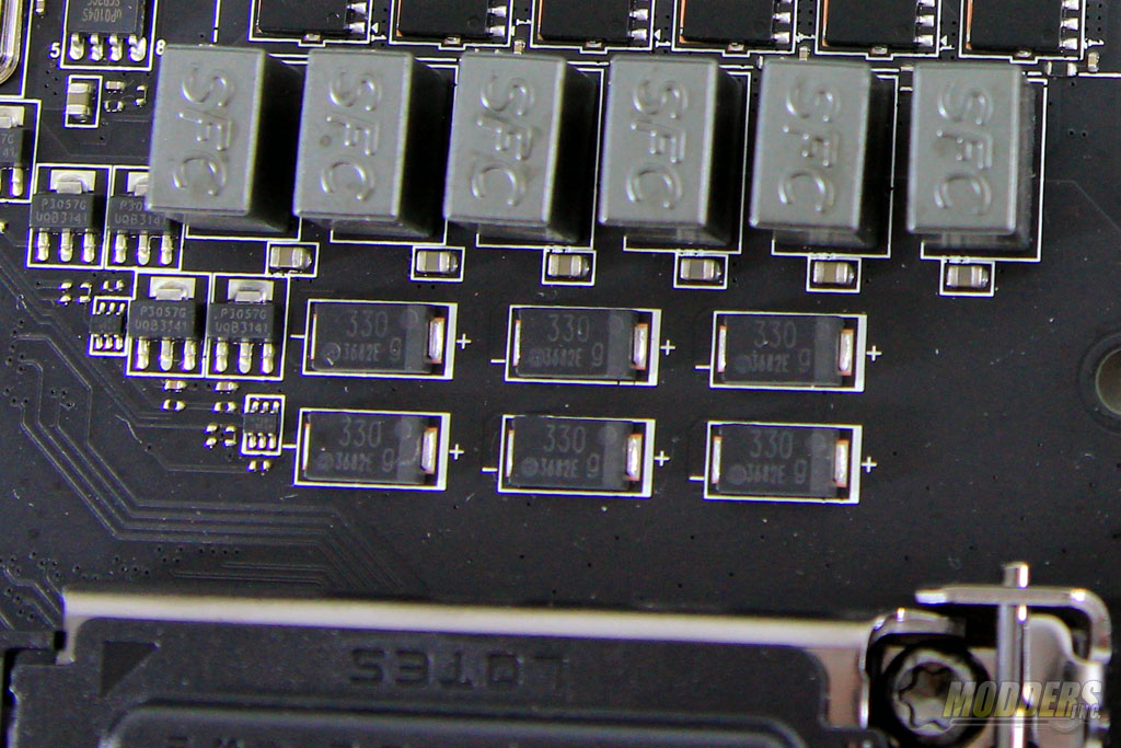
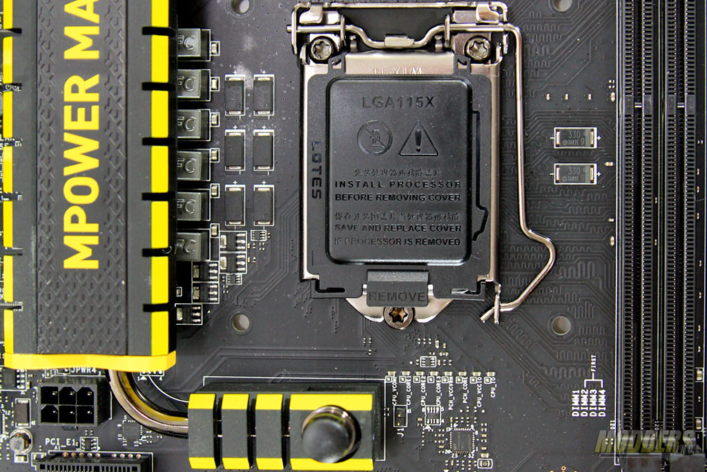
The inductors are 0.47uH “Super Ferrite” chokes and the surrounding capacitors on the CPU area use the same Tantalum-core Hi-c caps used on MSI’s high-end motherboards which are convenient for LN2 overclockers because their low-profile design makes it very easy to insulate (with Dragon Skin or kneaded eraser) the surrounding CPU area. The rest of the capacitors are solid aluminum-core Low-ESR “Dark Cap” capacitors.
The CPU socket itself is an Intel LGA1150 socket supporting current Haswell processors such as i7-4770K but also upcoming Haswell refresh processors out of the box without any need for a BIOS update. Standard 24-pin and 8-pin CPU power connectors are available but auxiliary power for the CPU (4-pin) and PCI-E (6-pin) can also be provided for advanced overclockers. Right below the CPU socket, MSI also provides an IDT 5V49325NLG clock generator for flexible BCLK adjustments with additional labeled voltage read-out points right above it.
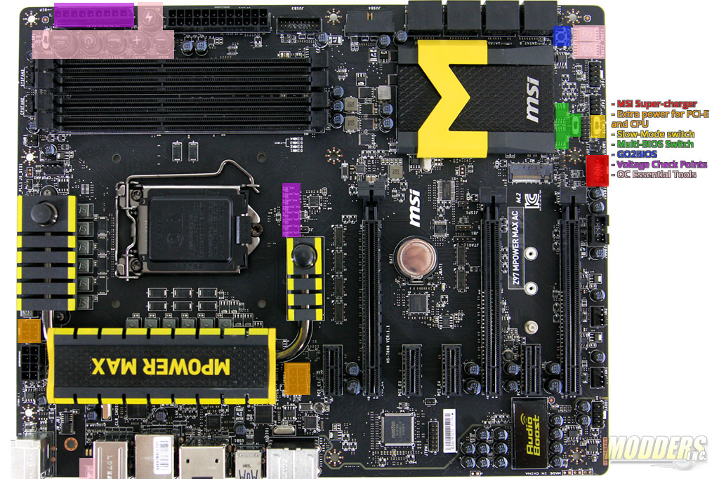
Speaking of convenience, several more MSI exclusive features are highlighted in the image below:
RED – MSI Super Charger – Internal 9-pin USB 2.0 port that provides quicker USB charging. This feature requires the Super Charger application to be installed on the operating system level before it can be enabled. Super-charger mode is also automatically enabled when the system is in standby or hibernation mode.
ORANGE – Extra PCI-E and CPU Power– For extreme overclockers who require more power for CPU and PCI-E overclocking, additional power input connectors are available.
YELLOW – Slow-mode Toggle Switch– Slow-Mode toggle switch – Useful feature for LN2 overclocking, allowing users to bypass CPU load during Windows OS boot by lowering CPU ratio and Vcore.
GREEN – Multi-BIOS Switch– Since the MSI Z97 Mpower MAX is an enthusiast mainboard, a redundant BIOS solution is available. Unlike mainstream motherboards however, the secondary BIOS does not automatically step-in incase of failure but has to be manually toggled.
BLUE – GO2BIOS– A convenient option for entering the UEFI without having to mash the DEL or F2 key (or if using some Gaming keyboards which are not recognized outside of the OS level). When pressed, the motherboard enters the BIOS upon boot hands-free.
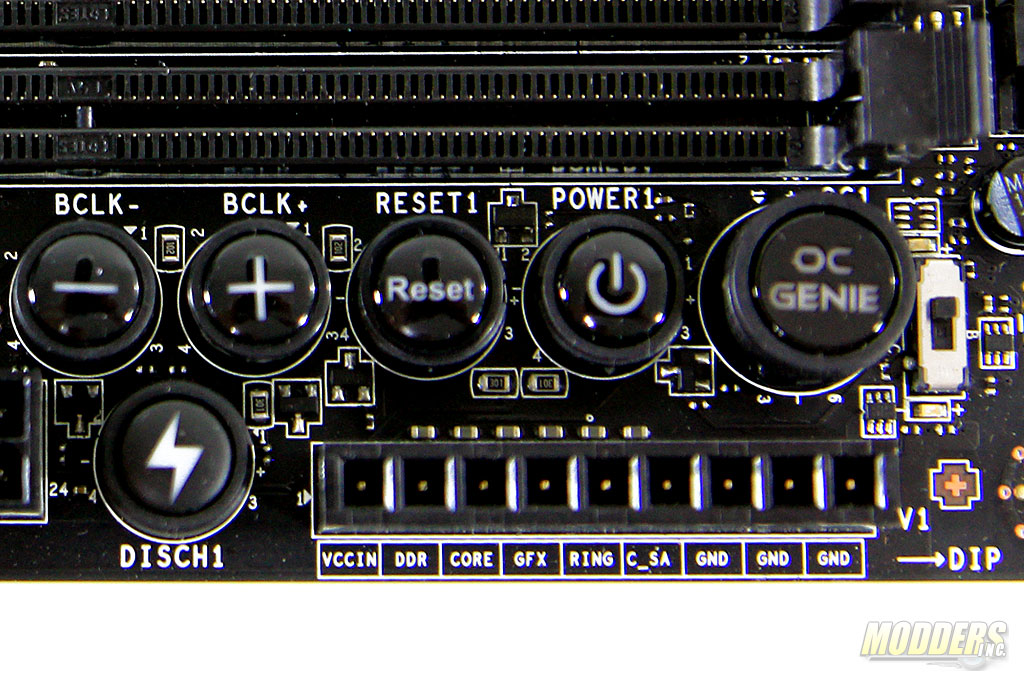
VIOLET – Voltage Check Points– Available on the top right side edge with voltage points for CPU, System Agent, CPU Ring, Integrated Graphics, CPU Core 0 Voltage, Memory Voltage, VCCIN, and three ground points. MSI also provides extended V-check point cables in the bundled accessory pack. Additional voltage readout points can be found near the CPU area as well.
PINK – OC Essential Controls– A collection of on-board overclocking features comprising of:
- OC Genie and Gear Switch – Auto-overclock button paired with a toggle switch with two gear settings.
- Discharge Button – Alternative to CMOS battery removal, pressed when the system is off.
- Power and Reset Button
- Base Clock Buttons – BCLK plus and minus buttons provide single-step adjustment and can be used while the system is running.
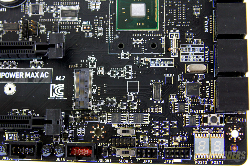
- Debug LEDs – A two-digit readout LED on the lower right hand corner that produces troubleshooting codes when necessary. On normal desktop usage, the CPU temperature is displayed instead.
- CMOS Reset button – Located in the rear IO, the CMOS reset button is recessed to prevent any accidental button press.
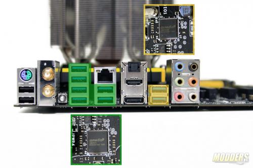
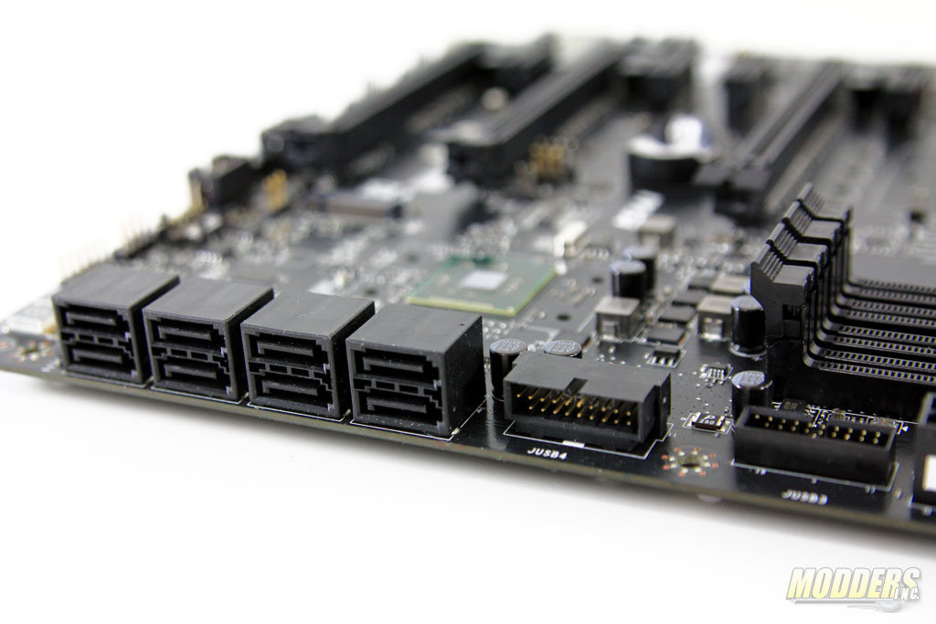
Two 19-pin front panel USB 3.0 ports are provided onboard by the Intel Z97 chipset. One of the headers is angled parallel to the board while the other sits vertically. Extra USB 3.0 ports in the rear I/O are handled by an ASMedia 1074 and and ASMedia 1042A chip. The ASM1074 is a device controller, taking two USB 3.0 ports from the Intel chipset and makes it six USB 3.0 outputs for the rear (up to four downstream per). The ASM1042A is a host controller which takes one lane of PCI-E from the Intel Z97 chipset and provides a pair of USB 3.0 per lane. So with the four USB 3.0 ports provided onboard and six provided by the ASM1074 and two more provided by the ASM1042A, total USB 3.0 port count is a very generous twelve. ASM1074 is also UASP compliant so it can take advantage of faster speeds with compatible enclosures or drives. MSI has also outfitted the Z97 MPOWER MAX AC with ASMedia 1464 signal repeater switches located at the back of the Intel Z97 USB 3.0 onboard headers. These chips optimize the signal performance and prevent signal degradation.
The SATA ports are similarly angled parallel to the mainboard surface like one of the USB 3.0 headers. This was done to provide SATA installation support even when video cards are installed. The top six SATA3 ports are provided natively by the Intel Z97 chipset (SATA port1 to 6) while the bottom two ports (ports 7 and 8) are from an ASMedia 1061 PCI-E bridge controller, meaning it takes one of the available PCI-E x1 lanes from the Z97 chipset and provides two SATA3 ports.
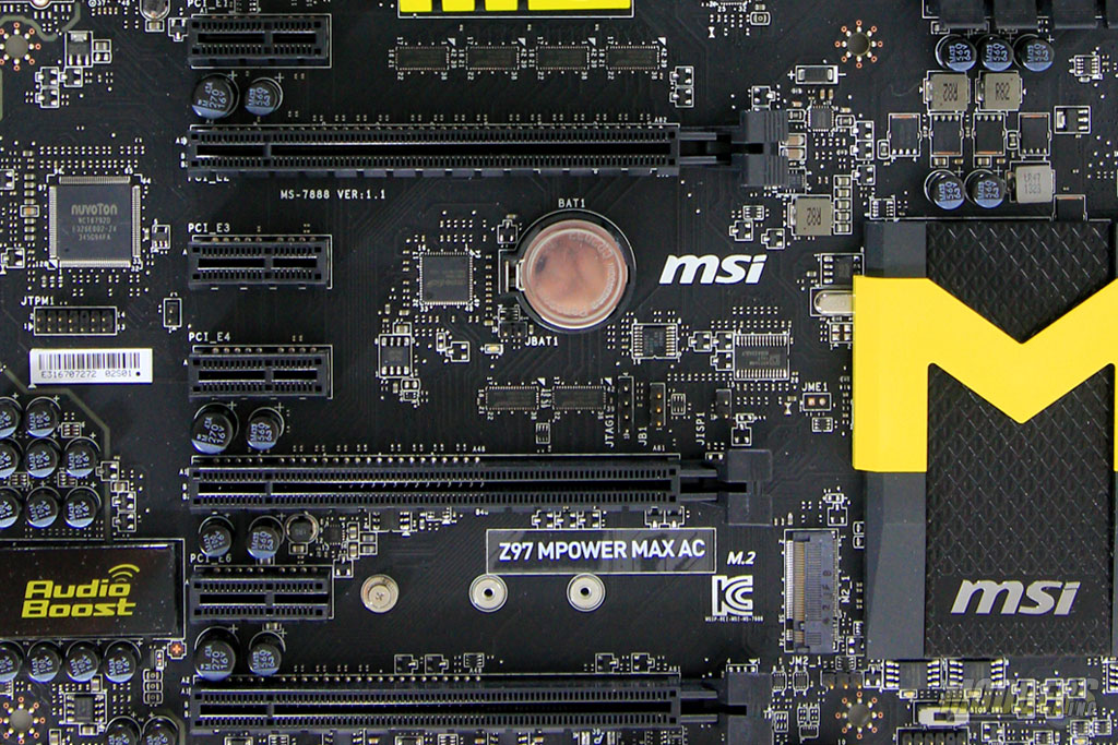
Like all MSI OC-series Z97 motherboards, there is an M.2 SSD port capable of up to 10Gb/s compared to the SATA bottleneck of 6Gb/s and supports 42mm, 60mm and 80mm long modules. This M.2 port is located in between the second PCI-E x16 slot and the third PCI-E x16 slot and shares bandwidth with the Intel SATA3 ports 5 and 6, so those two ports cannot be used when the M.2 port is populated. An M.2 to SATA-Express adapter is also available but it has to be purchased separately and is not included in the accessory pack. This is a similar design with the Z87 MPower MAX (which used one SATA3 port for the mSATA) but with two SATA3 ports instead of pulling two PCI-e x1 lanes for the M.2 like other Z97 motherboards.
Expansion slot distribution is as follows, in order from top to bottom:
- PCI-E 2.0 x1 slot
- PCI-E 3.0 x16 slot (16x when populated by itself, 8x when more graphics cards are installed)
- PCI-E 2.0 x1 slot
- PCI-E 2.0 x1 slot
- PCI-E 3.0 x16 slot (8x mode or 4x when the 3rd PCI-E x16 slot is populated)
- PCI-E 2.0 x1 slot
- PCI-E 3.0 x16 slot (operating at x4 mode)
Up to three Radeon video cards in Tri-CrossFireX mode is supported in 8x/4x/4x while up to two GeForce video cards can be installed in dual-SLI 8x/8x mode.
Along the bottom edge, starting on the right side sits the front panel connectors for case installation. Users can use the provided M-connectors for easier installation. Two USB 2.0 9-pin headers are provided on the bottom edge, but the red header is for the MSI Super-Charger port. The pin-out for the front panel connectors is also printed on the PCB, although this is obscured by the Intel Z97 chipset heatsink.
All five fan headers on the MSI Z97 Mpower MAX are 4-pin PWM connectors. Two are provided for CPU fans and three are provided for system fans. There is no DC fan control for 3-pin fans however as I have tried it with the Phanteks 140mm fans on my heatsink. The fan location is highlighted below in BLUE for convenience:
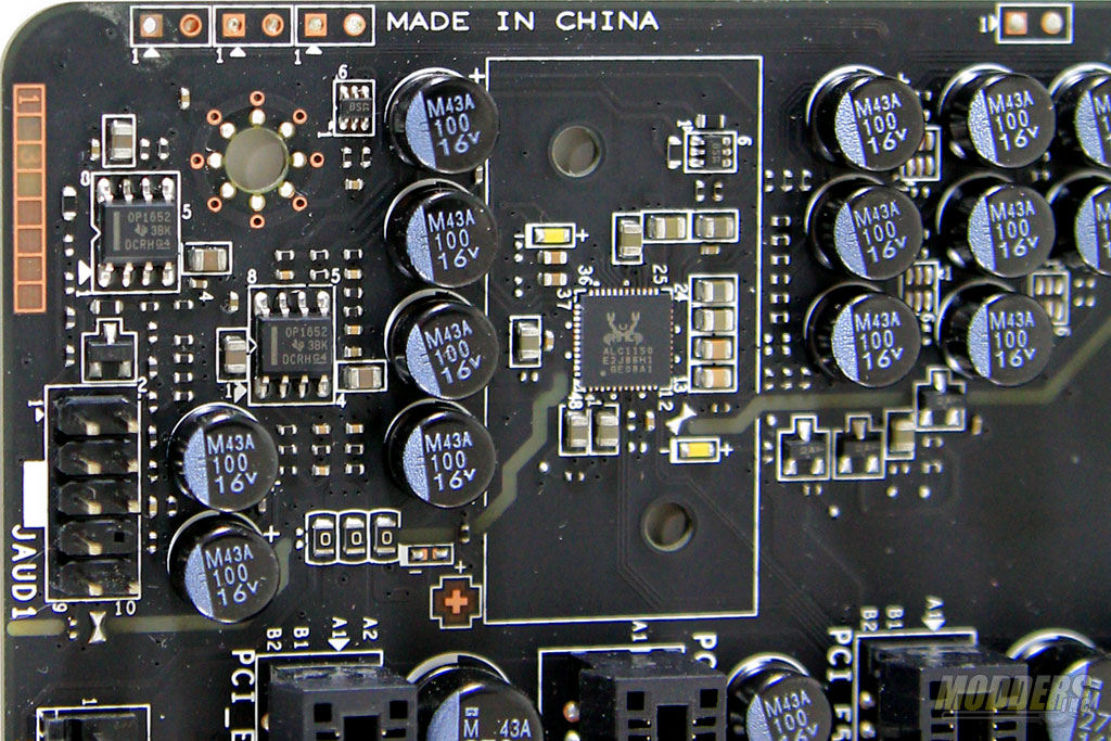
Just like the Z87 Mpower MAX, the Z97 version’s audio area is isolated from the rest of the motherboard. The Realtek ALC1150 codec is shielded as well to minimize interference. The cover is now removable from the back, which looks a lot better compared to the unsightly screws of the Z87 version. In this isolated area also sits Texas Instruments OPA1652 dual-channel OpAmps, delivering filtered and amplified signal outputs.
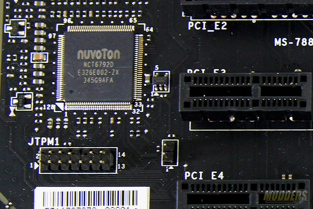
The big chip right behind the second PCI-E x1 slot is a Nuvoton NCT6792D Super I/O, responsible for hardware monitoring functions, fan speed control and legacy PS/2 port for mouse and keyboard.
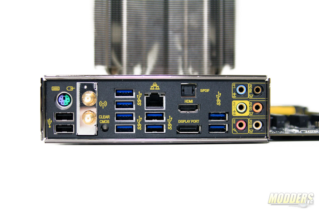
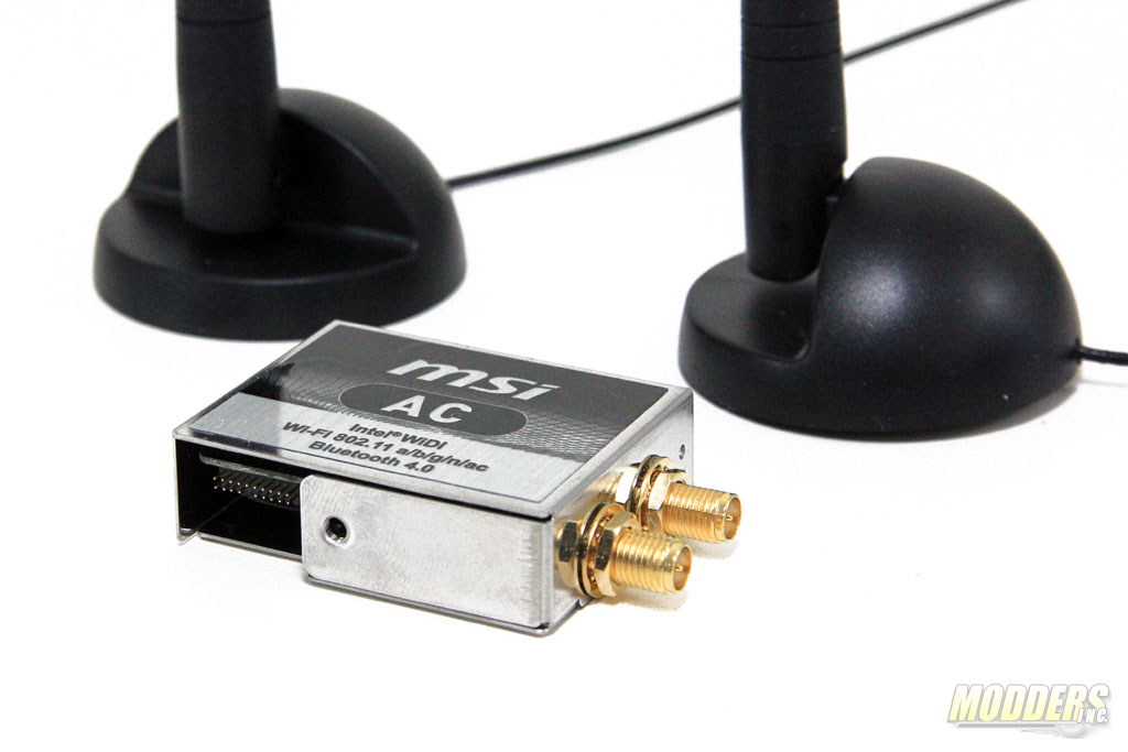
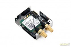
At the rear IO, HDMI and DisplayPort outputs are available for the integrated Intel graphics display supporting up to 4096×2304@24Hz. An optical SPDIF output port is also located above these. Wired network connectivity is provided by an Intel i218V Gigabit controller while a detachable Wireless AC module can be installed between the rear USB 2.0 ports and the clear CMOS button.
The wireless module houses an M.2 2230 version of an Intel Wireless-AC 7260 adapter. It supports dual-band, 2×2 802.11ac, dual mode Bluetooth 4.0, and Intel Wireless Display. The pair of antennas now use SMA connectors that screw into the module instead of the push-in type but other than that, their design remains the same compared to the Z87 MPower MAX, retaining the useful magnetic base and adjustable angle.



Good job, liked the attention to detail in your review like the electronic components used, allost noone is doing that these days they are most show off marketing than proper reviews. Thx
Thank you very much for reading. We are always trying to improve our reviews so reader feedback is always welcome. Cheers, –Ron
Great review!, love that you put time into looking what the power delivery system is on this board. They downgraded from the 20 to 12 and changed the components of it, my question is; Is this worse or better than the old power delivery system of the Z87 MPOWER (MAX)?
Hello, thanks for reading. I am fairly conservative when it comes to economics and design so I don’t fault them completely for doing that. Also, MSI is not the only one who scaled back with the design on their boards, which I think is much efficient anyway given current and upcoming CPUs. Hybrid plus less capacitors understandably is harder to accept after seeing the last model but I have a feeling we will see less and less monster VRMs from all manufacturers. I am not an LN2 overclocker so unfortunately I cannot speak with authority on how grossly this is affected but on air, I don’t think it is an issue IMO. The Z87 Mpower MAX AC is still the better deal of the two currently ($239 on NewEgg) hence I did not give the Z97 version an Editor’s Choice award.
Technically is a kinda of an upgrade since previous generation used a 5 true phases design with quadruples (5×4=20 hybrid phase design) and it was controlled by a digital high quality IR3563B PWM, now they use 6 true phases with doublers/drivers package (6×2=12 hybrid phase design) but with a ISL6388 PWM witch is a new product with no much info about it and products from ISL usually are hybrid analog/digital controler witch is not better than fully digital and for that is also a kinda of downgrade but still needs confirmation. The rest of the components mosfets and inductors seems to be as equal quality as from previous generation. In real world this only appears to affect price that seems pretty good for the features and power delivery is more efficient no doubt on that. MSI is pretty solid manufacturer and a lot bigger than most people think.
It seems to be that ISL6388 is Intersil’s first fully digital controller. I have no clue if it is in indeed an upgrade.
Is there any difference on mpower and mpower max? For a average game/media use? maybe some slight overclocking too? Hows the PWM or such compared to each other?
The PWM design is the same, judging by photos from XFastest’s Review: http://www.xfastest.com/thread-135126-1-1.html
Looks like the difference is just a few features: fewer USB 2.0 and 3.0, lack of fixed MOSFET heatsink barbs, WiFi, e-SATA and additional HDMI for Intel graphics.
I hope this won’t go unnoticed
On the Intel Chipset heatsink, with the big M, is that thermal paste? Or is it some kind of thermal compound?
It is solid (albeit soft), flat and very thin tape at room temperature. It is closer to thermal compound in terms of moisture than the drier pink thermal tape used on other chipset heatsinks which leaves harder to remove residue (ASUS Z87 RoG chipsets).
Oh, good. If i take off the heatsink, do i have to replace or change it? I intend to paint the heatsink, but i dont know what to do with the thermal compound/pads.
You can scrape it off completely and just replace it with thermal paste or a thin thermal pad. The chipset itself has a very low TDP ~5W so cooling it is not really going to be difficult.