MSI Z170A MPOWER Gaming Titanium Review: Heavy Metal Magnificence
A Closer Look at the MSI Z170A MPOWER Gaming Titanium Motherboard
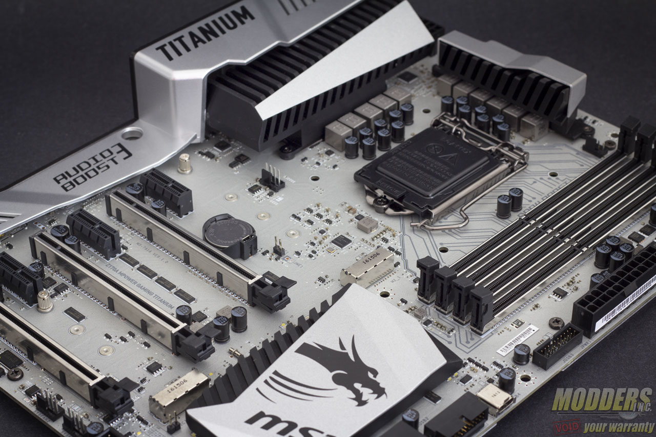
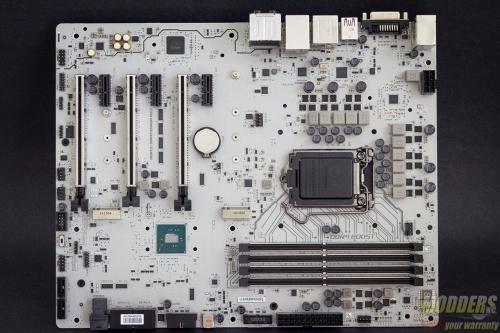
While it is easy to see why the MSI Z170A MPOWER Gaming Titanium is appealing from afar with its fine speckled silver coat, sleek metal covers and a sprinkling of sophisticated black elements, it is even better fully appreciated up close and in the nude. Although disrobing this beauty is not as easy as it seems since it wears a weighty apparel.
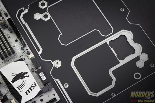
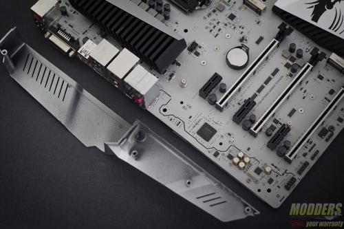
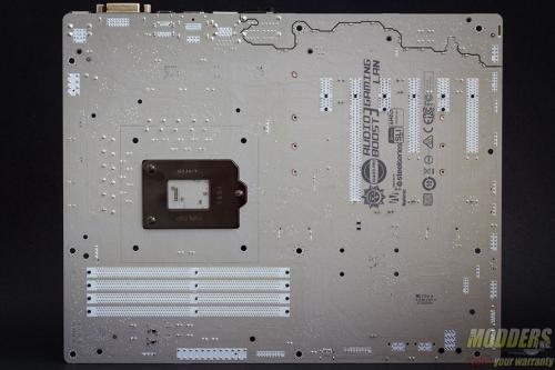
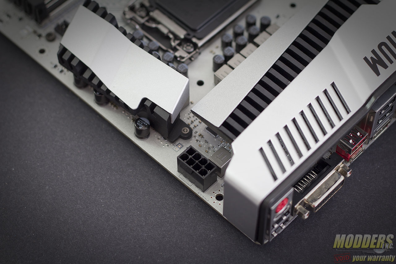
The integrated metal backplate alone weights 431 grams, while the rear IO cover made of lighter weight plastic weighs 30 grams. The largest CPU VRM heatsink towards the left of the CPU socket weights 157 grams while the smaller one at the top weights 76 grams. Rounding out the rest of the set is the chipset heatsink weighing in at 118 grams. That is a total of 812 grams without the motherboard PCB itself.
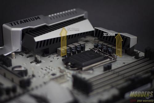
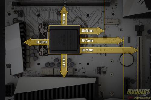
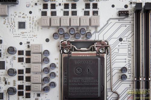
The Z170A MPOWER Gaming Titanium is a more affordable version of the Z170A XPOWER Gaming Titanium previously released, so there are some differences in terms of features as well as components used. Most notable around the CPU socket are the absence of their low profile HI-C caps and the use of solid capacitors instead. These are hardly deal-breakers performance-wise but they do sit too close for comfort around the CPU socket area. Users of larger CPU pump block AIOs without sufficient elevation will face clearance issues (such as those using the 1st version of Cooler Master’s new MasterLiquid 240).
To keep the cost much more affordable than the XPOWER Gaming Titanium, MSI has also omitted onboard OC features such as buttons but keeps some of the OC essentials such as slow-mode for LN2, voltage read-out points (albeit simpler), Port-80 debug LED and component function debug LED.
The main PWM controller is an uP9506, a 3+2 phase capable IMVP8 controller from UPI Semiconductor for the CPU+GT. There are three integrated drivers in total on this controller, all of which are used with additional drivers for the NIKOSemi PK616BA and PK632BA MOSFETs. Output filter has custom 420nH “Titanium” chokes with 560uF Japanese FP caps. Right below the CPU socket, MSI also provides an IDT 5V49325NLG clock generator for flexible BCLK adjustments.
The 8-pin EPS12V CPU power connector is at the top right corner, right above the VRM heatsink with the latch facing upward so it is easier to release later during uninstallation.
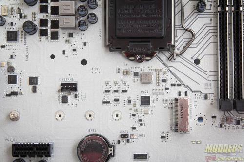
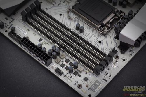
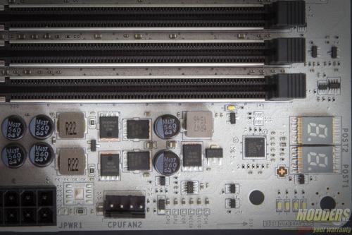
The DIMM slots have a steel “armor” around them and lock on both the top and bottom end part. A Powervation PV3205 dual-phase controller is used for the memory VRM a NIKOS PK616BA and NIKOS PK632BA per phase. The port-80 debug LED is placed right above this PWM controller with the function debug LEDs right beside it. Further down near the MOSFETs are the voltage read-out points and the second CPU fan header (while the first one is right between the top VRM heatsink and DIMM slot). This is an interesting position as most secondary CPU fan headers are located very close to the first one.
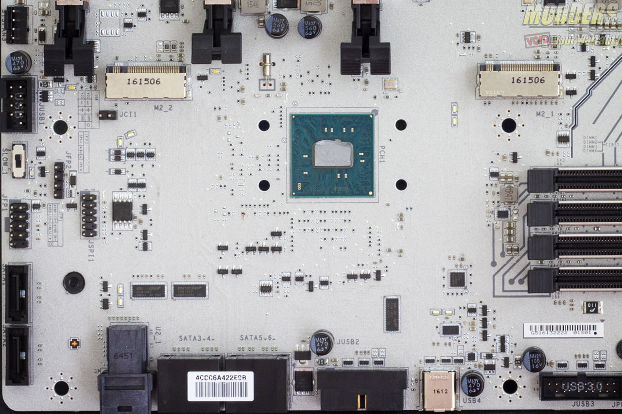
Onboard storage begins with a 19-pin USB 3.0 header right below the 24-pin power supply connector and there is one more right beside the chipset heatsink angled parallel to the motherboard. A USB USB 3.1 Gen1 (aka plain old USB 3.0) Type-C connector is also available here, all three are natively from the chipset although MSI uses ASMedia 1464 redrivers to maintain the integrity of the connection over longer cables.
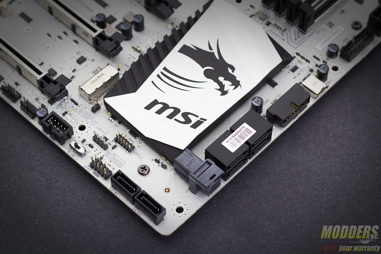
Provided for SATA drives are six SATA3 headers, two pairs of which are angled beside the angled USB 3.0 header, while two more are at the lower corner edge facing upward. What is exciting however is the inclusion of an embedded U.2 connector.
Two M.2 slots are available although the one at the bottom does not support 110mm long devices because it is right beside one PCI-E x1 slot. The top-most M.2 slot can freely use one however.
| M.2/U.2/SATA Combination Table | ||||||
| M2_1 | PCIe/Empty | SATA | PCIe/Empty | SATA | PCIe/Empty | SATA |
| M2_2 | PCIe | PCIe | SATA | Empty | Empty | SATA |
| U2_1 | No | No | No | Yes | Yes | No |
| SATA1 | Yes | Yes | No | Yes | Yes | No |
| SATA2 | Yes | Yes | No | Yes | Yes | No |
| SATA3 | Yes | Yes | Yes | Yes | Yes | Yes |
| SATA4 | Yes | Yes | Yes | Yes | Yes | Yes |
| SATA5 | Yes | No | Yes | No | Yes | No |
| SATA6 | Yes | No | Yes | No | Yes | No |
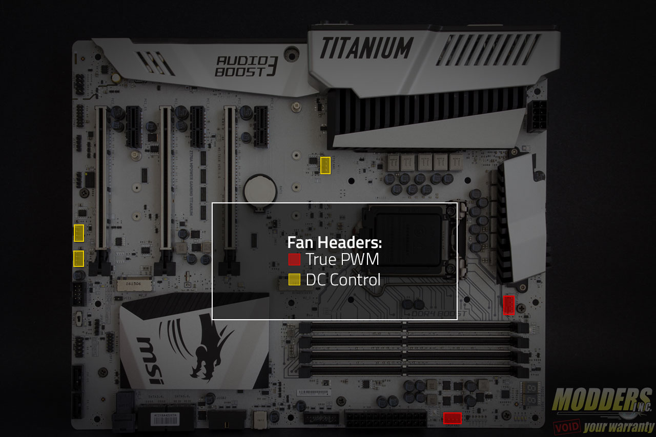
Aside from the two PWM fan headers, three more 4-pin fan headers are available; Two of which are at the bottom while one is right below the left VRM heatsink, ideal for rear exhaust fans in a mid-tower case. Although all are 4-pin fan headers, only the two CPU fan headers are true PWM with a GND, +12V, Sense and Speed control pin layout. The other three fan headers are voltage control fan headers.
Aside from storage options, the rest of the bottom front edge consists of the front panel header, slow mode toggle switch and 9-pin USB 2.0 header. What is unusual for an overclocking mainboard is the lack of redundancy for the BIOS as there is only a single Macronix 128-Mbit flash IC present, although there is clear CMOS jumper present.
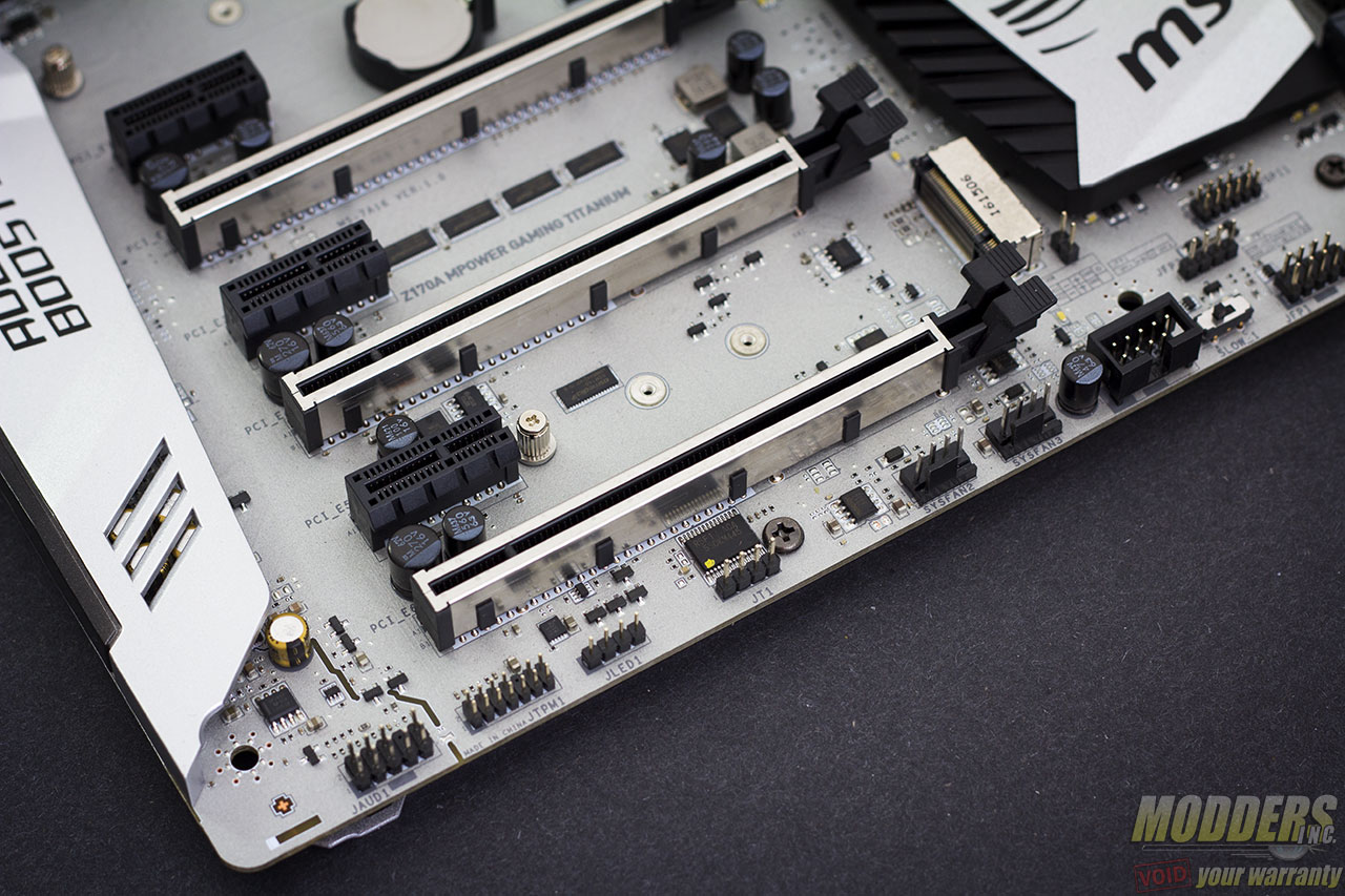
Expansion slot distribution is as follows (in order top to bottom):
- PCI-E 3.0 x1 via Z170
- PCI-E 3.0 x16 via CPU (x16, x8 when slot 4 is populated)
- PCI-E 3.0 x1 via Z170
- PCI-E 3.0 x16 via CPU (x8)
- PCI-E 3.0 x1 via Z170
- PCI-E 3.0 x16 via Z170 (x4, shares bandwidth with PCI-E x1 slots)
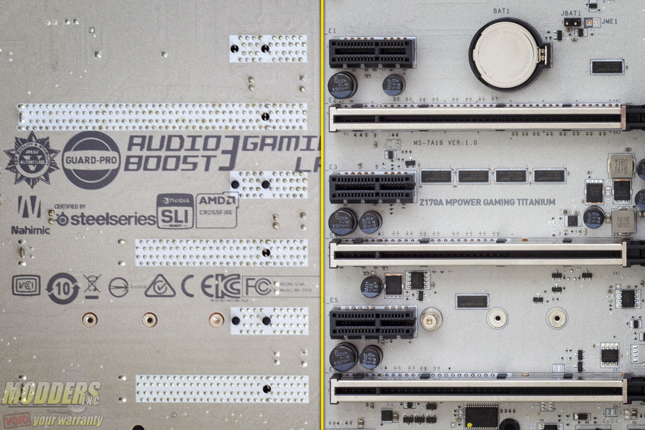
Like the DIMM slots, the Z170A MPOWER Gaming Titanium motherboard’s PCI-E retention slots are reinforced with soldered-through shielding. This prevents the motherboard from getting damaged just in case something heavy drops on your video card that dislodges it.
The rest of the headers along the bottom include a trusted platform module header, an RGB LED header and front panel audio headers. The RGB LED header is for connecting RGB LED strips which then can be controlled in sync with the MSI Z170A MPOWER Gaming Titanium via Gaming APP desktop software application.
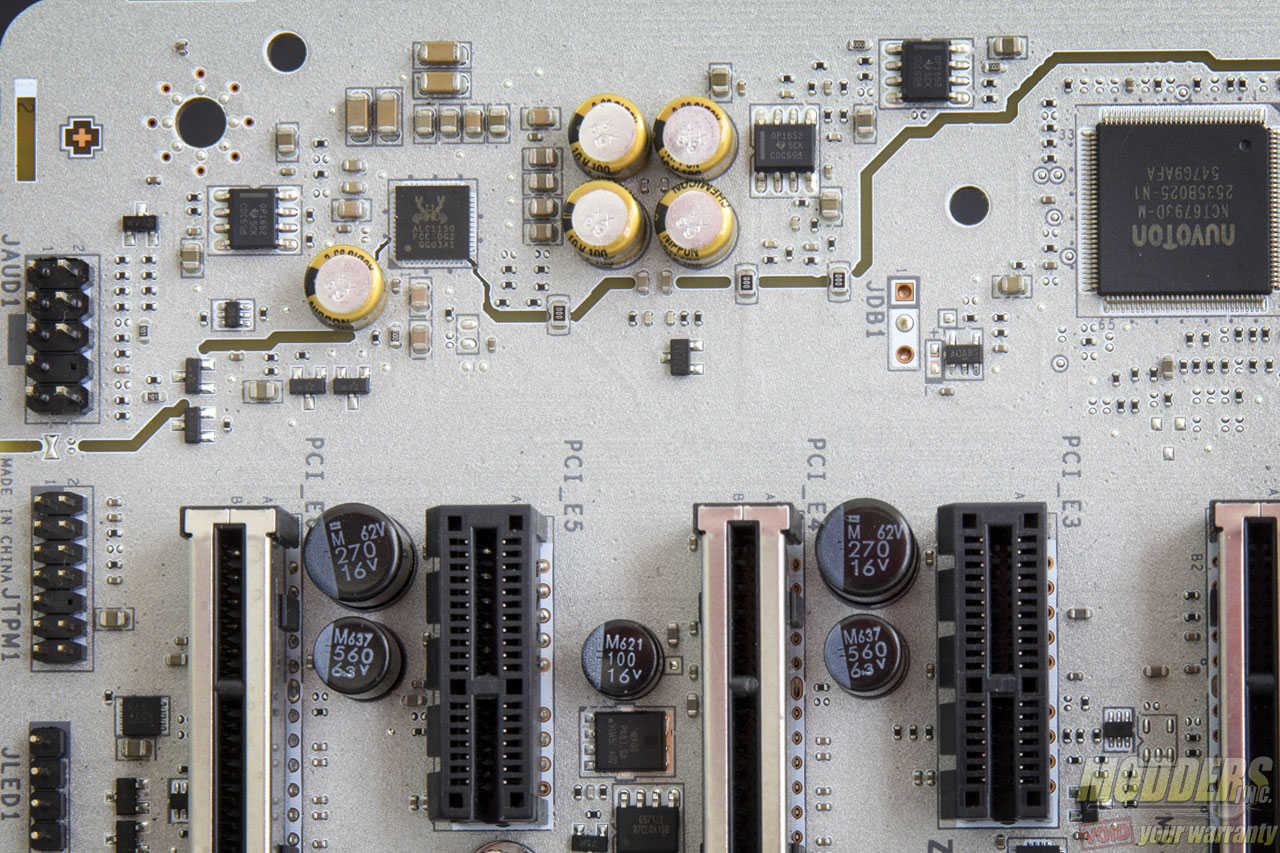
The audio subsystem is physically isolated from the rest of the PCB and audio is handled by a Realtek ALC1150 HD Audio codec. The ALC1150 has 115dB front DAC and 96DB DAC for the rest of the output channels and supports 24-bit playback/line in. This audio subsystem lights up with white LEDs lined up at the rear of the PCB that shine through the isolation border. Nippon Chemicon audio capacitors are used for filtering in this area and a pair Texas Instruments OPA1652 amp is used for the rear IO audio output which can drive up to 2k-ohm loads. The front audio gets one as well for headphones.
The big chip right behind the topmost PCI-E x16 slot is a Nuvoton NCT6792D Super I/O, responsible for hardware monitoring functions, fan speed control and legacy PS/2 port for mouse and keyboard.
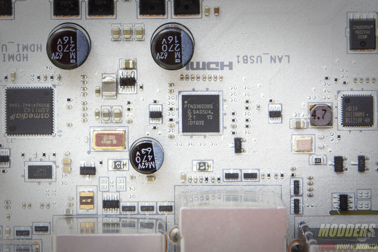
Intel’s latest “Jacksonville” i219-V is used for Gigabit Ethernet and this port with the pair of USB 3.1 Gen1 ports below it light up a red LED when the system is powered on. The other USB 3.1 ports in the rear IO are Gen 2 (10Gbps) via an ASMedia ASM1142 host controller which bridges a PCI-E 3.0 x1 lane to two downstream USB 3.1 ports, one is Type-A while the other is a Type-C reversible port.
Four more USB 2.0 ports are available in the rear IO from the Z170 chipset and the display output includes a DVI-D and an HDMI port with an NXP PTN13360DBS Level Shifter.
For rear audio, there are five configurable analog audio jacks with one optical audio out with all the analog jacks having gold plating on the connector end. THe rear output is color coded red while the rest of the jacks are all black. Thankfully, the IO shield is clearly labeled.
