MSI X99A Gaming 9 ACK Motherboard Review
MSI X99A Gaming 9 ACK Overview
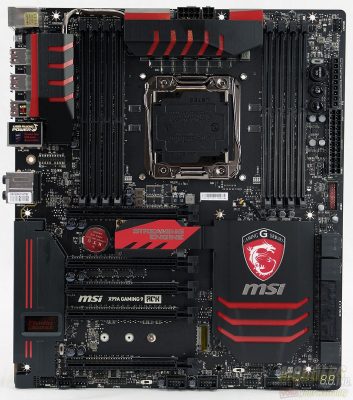
After wrestling the motherboard from the packaging, you’ll be presented with an EATX sized motherboard. The board is decorated in MSI’s gaming colors scheme. The black with red accents looks good and in my opinion isn’t over done. The motherboard measures in at 12 inches by 10.4 inches (30.5cm x 26.4cm).
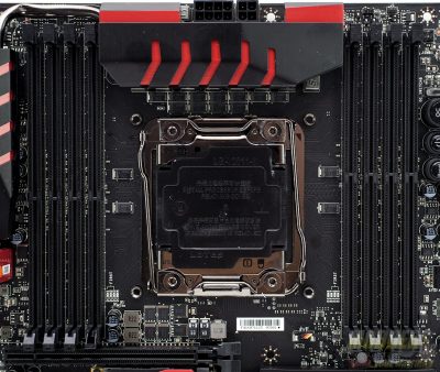
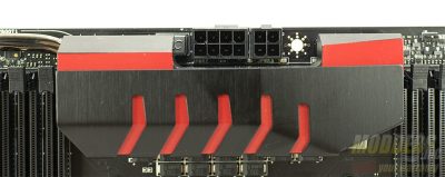
The area around the CPU socket is pretty clean. The only issue that I can see is the VRM heatsink may interfere with some of the larger air coolers on the market. Depending on the cooler and the memory modules used, cooler to memory interference may be an issue with the memory module slots closest to the CPU.
CPU power is provided by an 8-pin connector just above the VRM heatsink and an additional 4-pin power connector is available to supply even more power for higher overclocks.
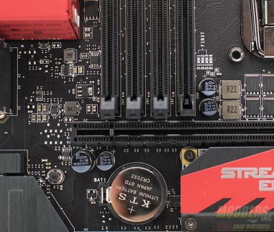
Some clearance issue may exist between the lower portions of the memory slots and the first PCIe slot if the GPU has a thick back plate. As you can see, I broke off one of the end caps on one of the slots. While this did not harm performance in any way.
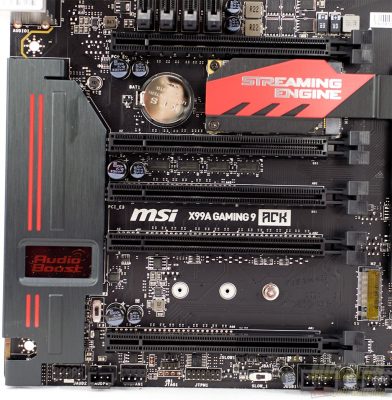
There are at total of five PCIe slots on the MSI X99A Gaming 9 ACK. Speeds are dependent on the CPU (28 lanes vs 40) and the slots in which the GPU(s) will be installed. With the Intel i7-5820K (28 lanes of PCIe available) installed the PCIe speeds will be x8,x8,x0,x8,04 and with the 40 lane CPUs the breakdown is x8,x8,x0,x16,x8
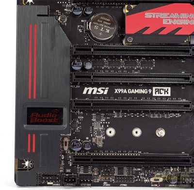
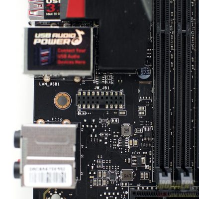
In between the last two PCIe slots is the M.2 SSD slot. This slot is fully capable of taking advantage of the new M.2 drives and uses a full x4 lanes. There is a small DIP switch that is located near the on board audio. This switch controls the power delivery. In one position, it uses the on board power and in the other position the audio chipset uses system power that is provided by a Molex connection and plugged into the header located at the bottom edge of the board.
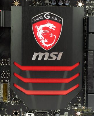
A large passive heatsink is used to keep the PCH cool and unlike the other X99 motherboards we’ve reviewed, is not connected via a heatpipe to the VRM heatsinks. The MSI gaming logo lights up on the heatsink when the system is powered on. Just below and to the left of the PCH heatsink is the dual BIOS switch.
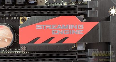
Connected to the PCH heatsink is the cover for the included Streaming engine. The card is recognized in Windows 8.1 as an Avermedia C353.
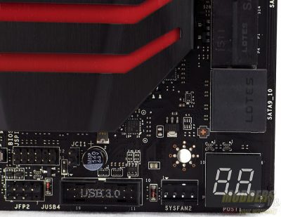
In the lower right corner is a LED display used to show diagnostic codes. The code descriptions are located in the user manual. There are two USB 3.0 headers on the motherboard. One is located near the LED display and the other is located near the 24-pin power connector. The bottom edge of the motherboard features the front panel audio header, two USB 2.0 headers, and the front panel controls such as power and reset.
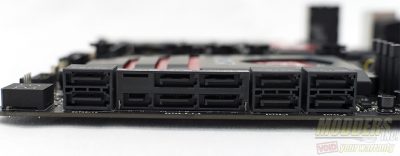
SATA connectivity is provided by the Intel PCH and features ten SATA ports and one SATA express port. When either the M.2 or SATA express ports are used SATA ports 5/6 are disabled.
The back I/O connectors feature a PS/2 Gaming port, two USB 2.0, six USB 3.0, two USB 3.1 (controlled via the ASM 1142 controller, gigabit ethernet, 802.11 AC wireless and 7.1 channel audio and digital optical out. A clear CMOS button is provided between the first two sets of USB ports in case an bad overclock causes the board not to boot.
Speaking of the back I/O, MSI included a wireless/bluetooth module with the X99A gaming ACK. This module plugs into the motherboard via a header in between the ethernet/usb ports and the audio port. The module is secured via a screw that is installed from under the motherboard.
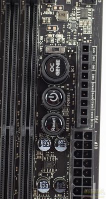
Moving to the top right corner of the motherboard are some addition I/O. Featured on this corner are a power and reset button as well as MSI’s OCGenie button. V-check connectors are provided near the edge of the motherboard. These are useful when you want to use a multi-meter to measure voltage to the various components vs relying on software to report voltages. The DIP switch near OCGenie button controls the CPU gear ratio and is extremely useful in maintaining high overclocks.
