MSI Core Frozr L CPU Cooler Review: Frozr Goes Vertical
Installation of the MSI CORE Frozr L
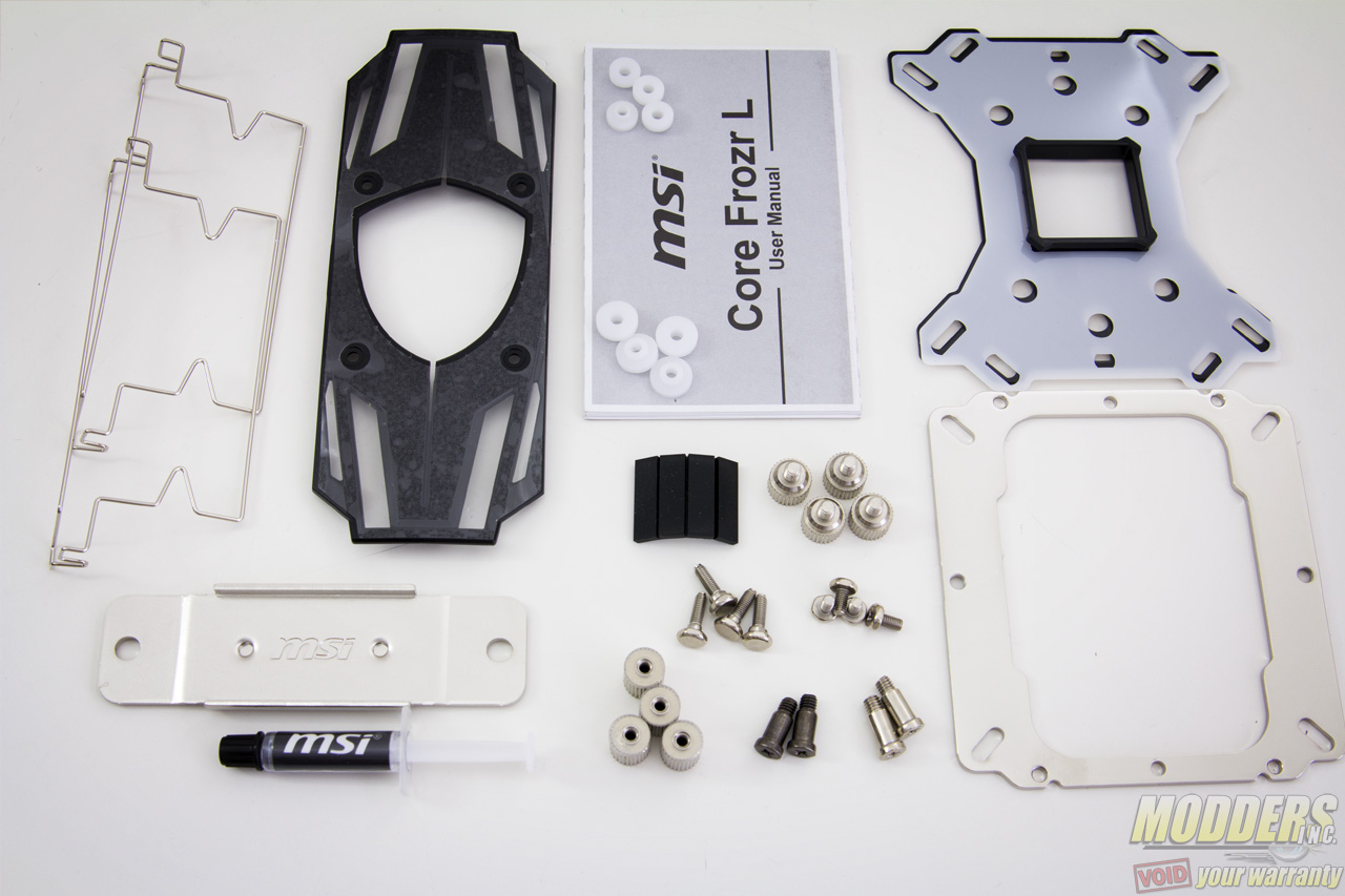
The mounting kit for the MSI CORE Frozr L looks a lot like a Thermalright cooler so it is most likely a shared OEM here. Considering Thermalright’s reputation, the MSI CORE Frozr L is in good company. Before proceeding with the installation, double check if all parts are accounted for and cross reference it with the fold-out user guide. Since it uses a universal backplate, both AMD and Intel mounting methods are similar with the exception of the backplate mounting holes used. For all installations, the bundled fan must be removed first.
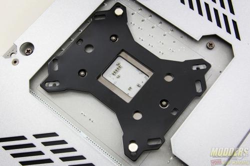
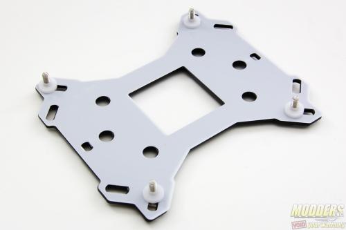
The first step is to attach the insulating film to the metal backplate then pin them together on the four corners via the post and washer combo for either AMD or Intel systems. AMD uses the larger washers and has a rectangular mount while Intel uses the smaller washers and has a square mount.
Since the washers are plastic, some might not fit as snugly on the stand-off post as others. If that is the case, attach the washer to the motherboard first then push through the post with the backplate. MSI uses double insulation here, making sure that the metal backplate does not cause a short on the motherboard at all.
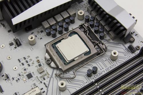
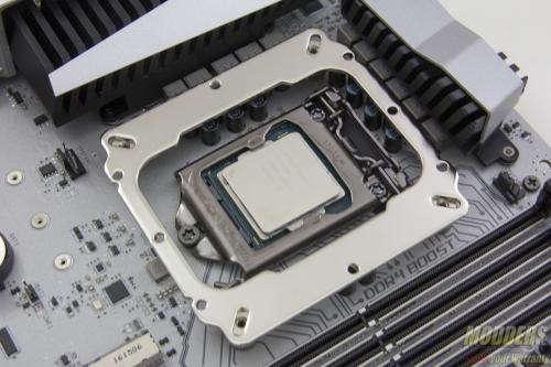
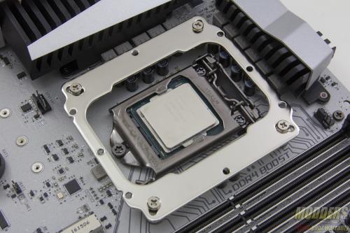
Once the backplate assembly has been put in place, use the locking nut mounts (which are insulated with plastic washers on one side) to secure it to the motherboard. Next is to position the anchoring mount on top and secure it to the nut mounts via 4x mounting screws.
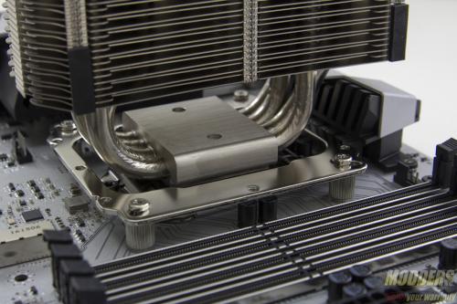
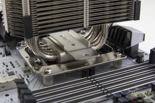
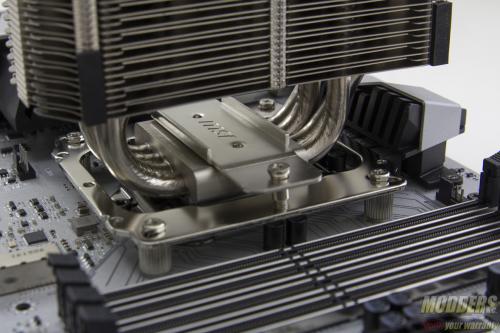
After the anchoring mount has been secured to the backplate assembly, remove the sticker cover on the CPU contact surface, apply thermal compound then position the mounting plate on the CORE Frozr L center. Slide the heatsink until the mounting holes on the mounting plate line up with the anchoring mount underneath it.
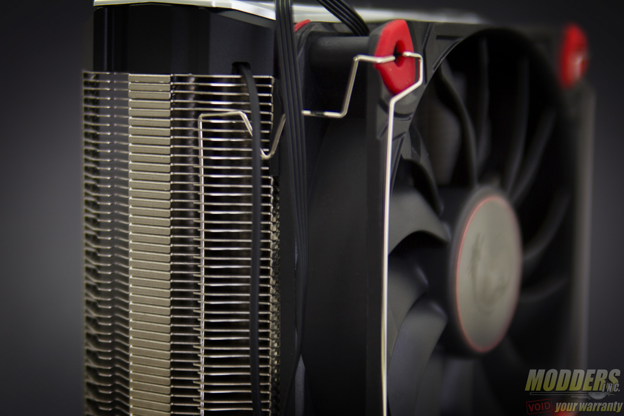
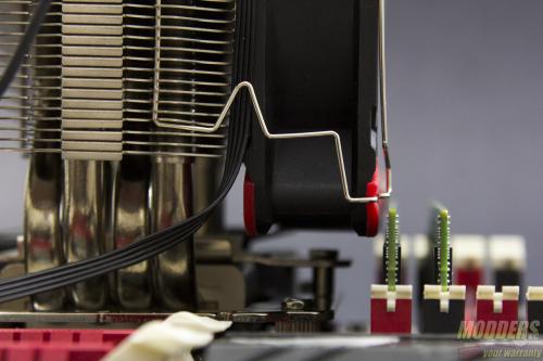
Once the mounting plate is fully secured, the last step involves re-attaching the bundled fan with the fan clips. The idea is to use the wide flat area of the clip and hook it to the designated latching point on the heatsink side. Then pull the front corners of the wire clip until the protrusion sinks in the fan mounting hole. Thankfully, the corners on this Torx fan are all padded so the fan frame does not get scratched.
Clearance Compatibility
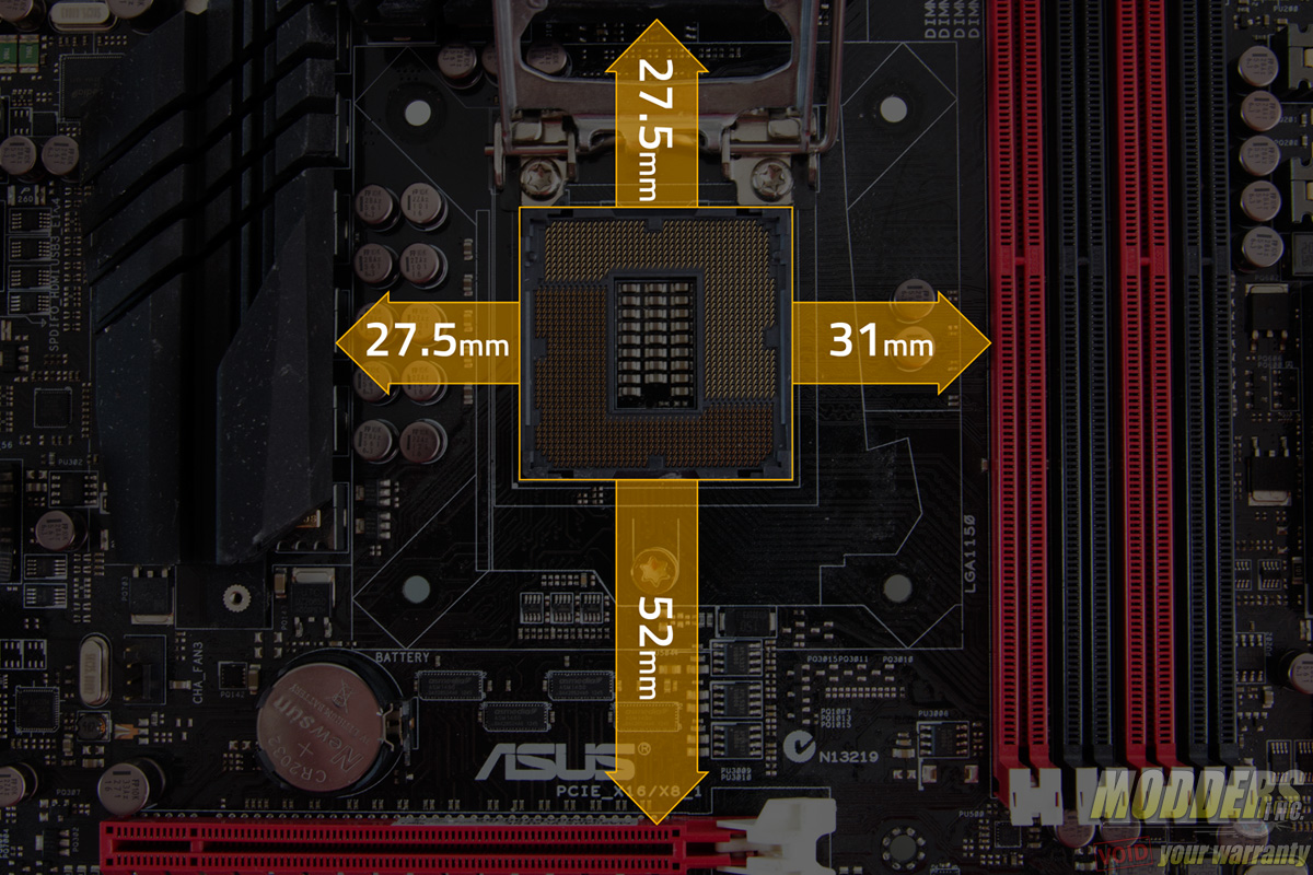
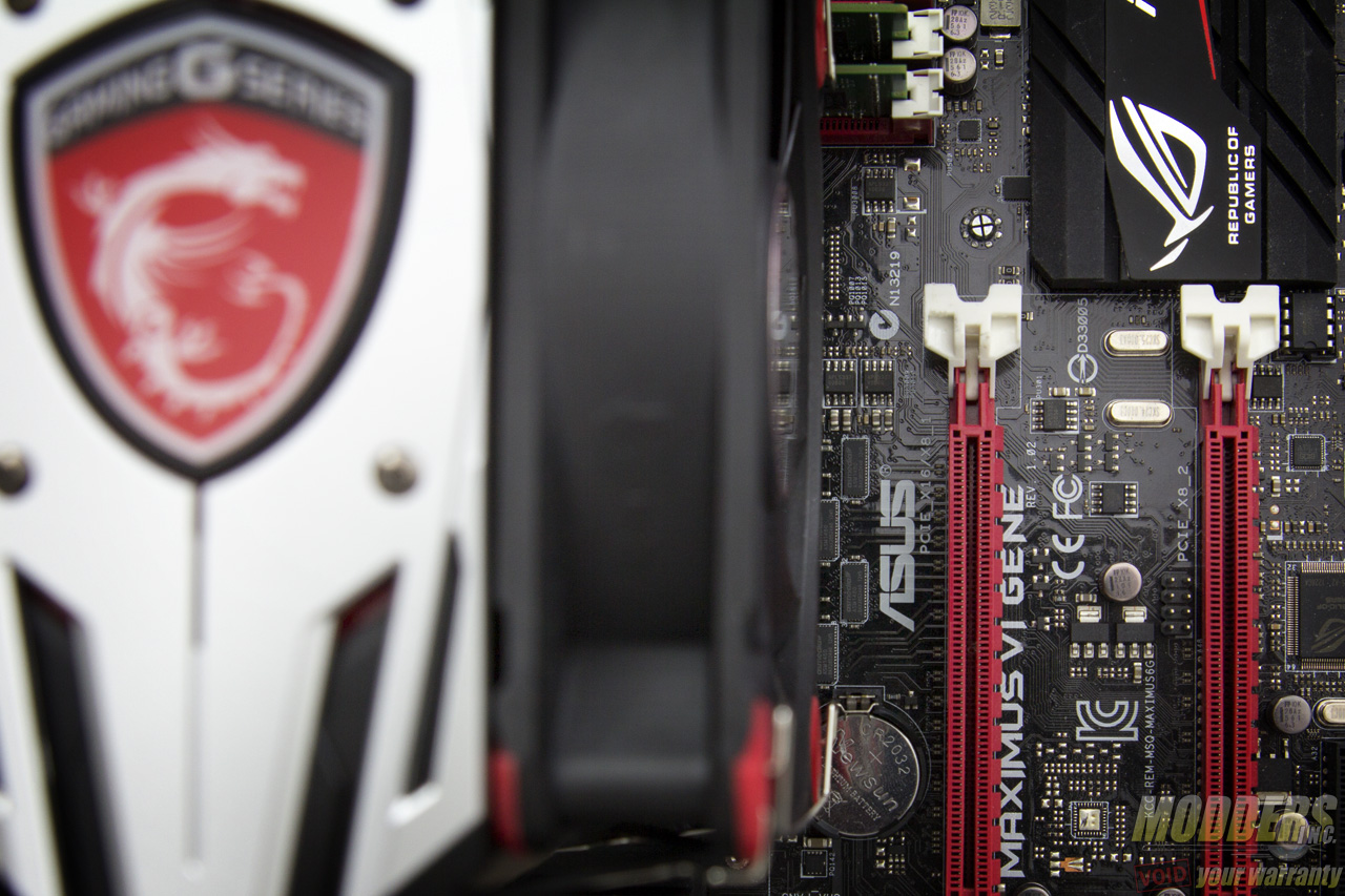
The test motherboard is an ASUS Maximus VI Gene micro-ATX motherboard and measuring from the edge of the socket (the gray plastic part), there is a 31mm gap between the CPU socket and the first DIMM slot as well as a 52mm clearance between the CPU socket and the topmost PCI-E x16 slot where the graphics card is installed.
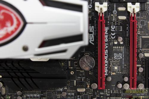
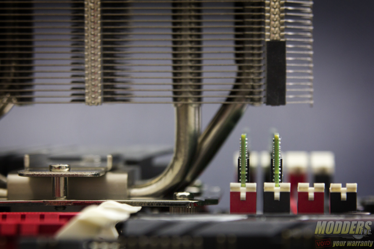
In the east/west orientation, PCI-E clearance poses no clearance issues because of the heatpipe offset allowing for extra clearance at the bottom. As for DRAM clearance, the fan clip sits too close for comfort to the very first DIMM slot RAM module in this motherboard although the fan itself is close but is completely clear from contact. Regular profile modules can still be installed after the fan has been mounted.
In a north/south orientation, the offset heatpipes allows for DRAM clearance cleanly. In the even that a north/south orientation is necessary but the VRM heatsink is on the way, there is still more than enough space underneath to fit a standard size DRAM module before it touches the heatpipe. Although the DRAM must be installed on the first DIMM slot first before locking the heatsink to the motherboard. If you absolutely must use a north/south orientation, just take advantage of the offset to clear the DRAM for compatibility instead.
PCI-E clearance even with a fan installed in the north/south orientation is not an issue however, due to the slim body design of the CORE Frozr L.
