MSI B85M Gaming Motherboard Review
A Closer Look at the MSI B85M Gaming Motherboard
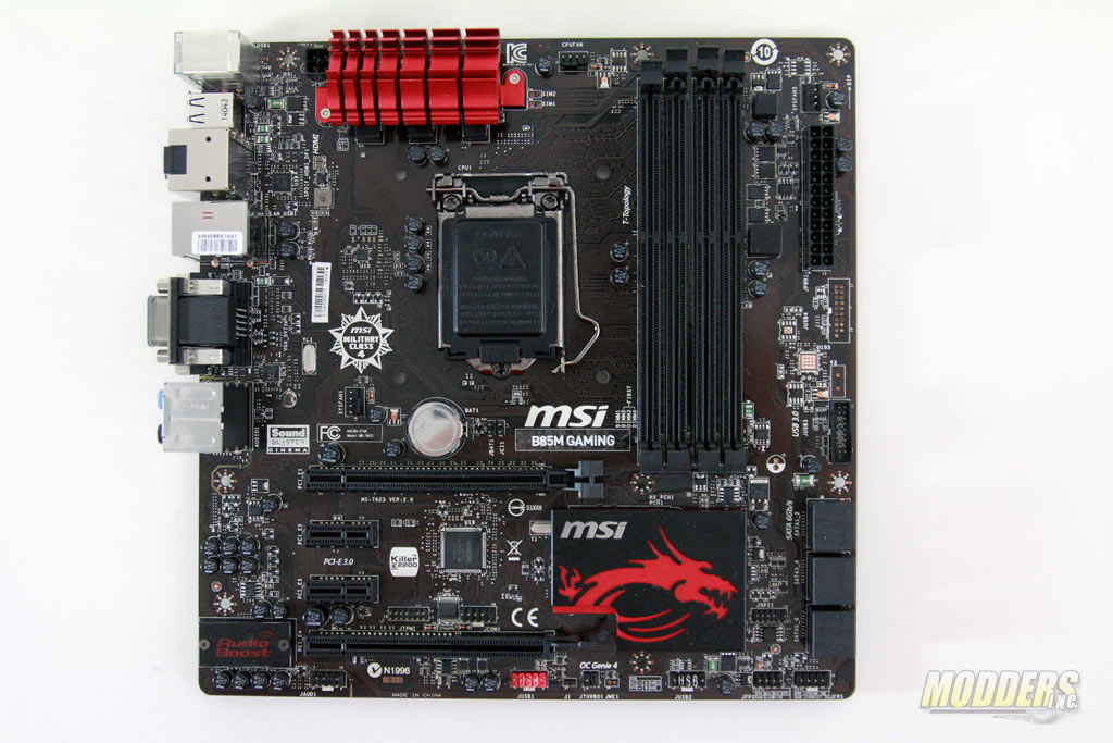
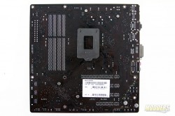
The MSI B85M Gaming uses a micro-ATX form factor measuring 244mm x 244mm on a 4-layer black PCB with visible brown surface traces. All the heatsinks, onboard ports and headers follow the black and red color scheme of the Gaming series.
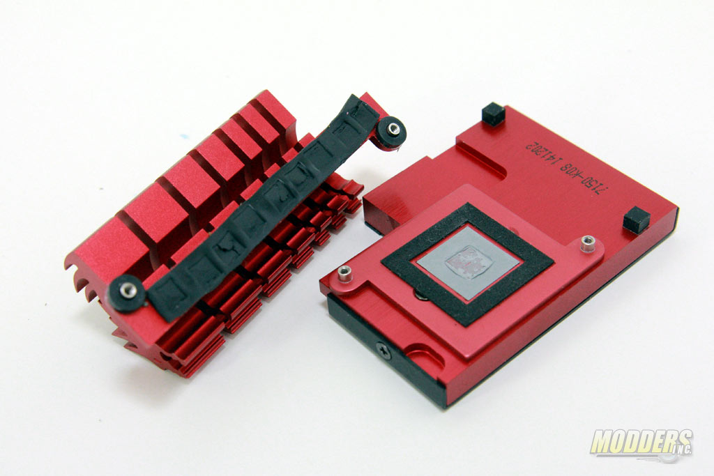
The heatsinks are held in place by spring-loaded screws and design-wise, they draw inspiration from the Gaming series dragon. Between the VRM MOSFETs and the VRM heatsink is a black thermal tape while the Intel B85 chipset uses thermal paste.
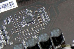
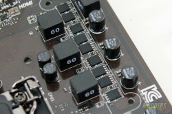
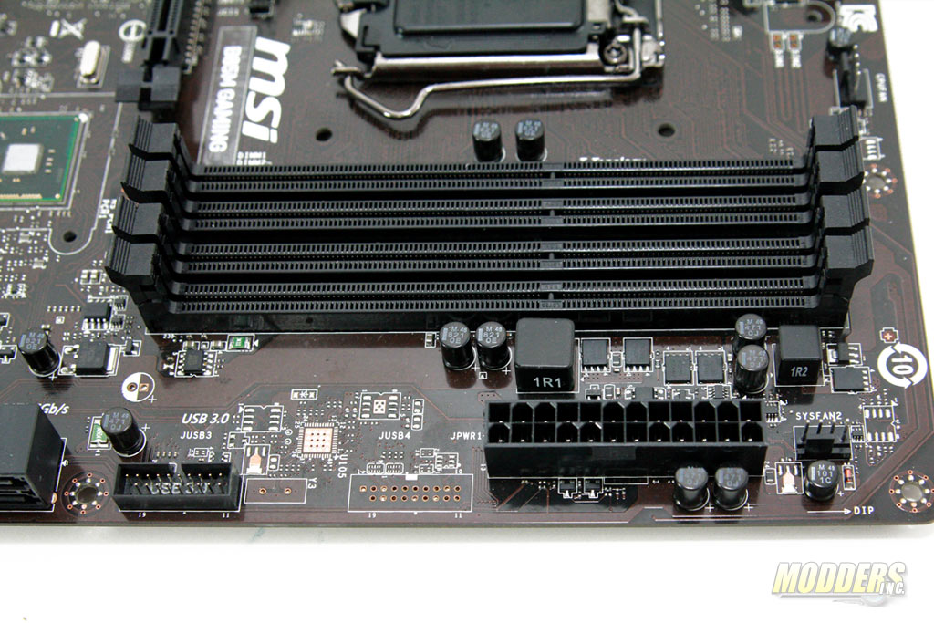
Earlier in 2014, Intel decided to lock out overclocking on non-Z motherboards and introduced a micro-code to prevent any tweaking. Since then, newer non-Z models released have an understandably much more modest power delivery systems. The B85M Gaming uses a 3-phase VRD12.5 Intersil ISL95182 PWM regulator with three ON Semiconductor NTMFS4C08N and three pairs of NTMFS4C05N Power SO-8 MOSFETs. The ISL95182 has two integrated drivers so a third driver is present on the edge. There are also three 0.60uH “Dark Chokes” and six 561uF solid “Dark Caps”. Unlike Z87 mainboards, the B85M Gaming motherboard only requires a 4-pin 12V P4 connector on the top left corner with the 24-pin ATX power on the right side edge.
The memory power is controlled by a single phase uPI Semiconductor 1504s and uses two NTMFS4C08N with two NTMFS4C05N MOSFETs and a 1.1uF inductor. Maximum memory support is 32GB across four DIMM with a maximum 1600MHz frequency.
Along the bottom edge starting at the right side are the two sets of front panel headers with the pin-out printed directly below them. A set of undocumented headers are located above these and behind the SATA3 ports labeled JSP1, which is for SPI flash programming (for MSI internal use only, not for end-users). There are also two 9-pin USB 2.0 headers, one of which is used for MSI Super-charger (the red one) while the OC Genie 4 jumper is located between them.
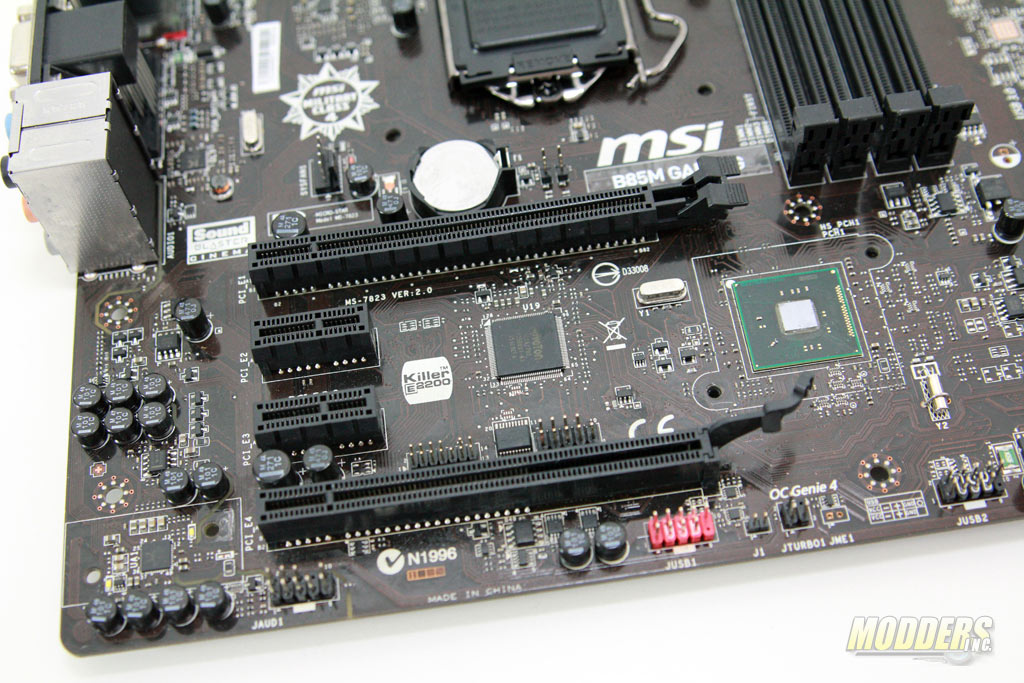
Expansion slot layout in (order from top to bottom):
- PCI-E 3.0 x16 slot (Operating at x16)
- PCI-E 2.0 x1 slot
- PCI-E 2.0 x1 slot
- PCI-E 2.0 x16 slot (operating at x4)
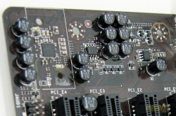
Expansion slots include a full-size PCI-E 3.0 x16 slot at the top and a full-size PCI-E 2.0 x4 slot with a pair of PCI-E 2.0 x1 slots between them. In front of the two PCI-E x1 slots are the Trusted Platform Module (TPM) header, a COM header and the Nuvoton NCT6779D SuperIO providing PS/2 support, HW monitor functions and fan speed control up to five headers.
As with the other Gaming series motherboards, the audio subsystem PCB is physically isolated from the rest of the PCB and a border starting from the front panel audio headers at the bottom up to the analog audio outputs can be traced. Underneath the EMI shielding is a Realtek ALC1150 codec with a Texas Instruments OP1652 OpAmp.
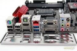
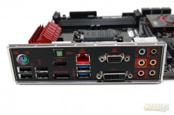
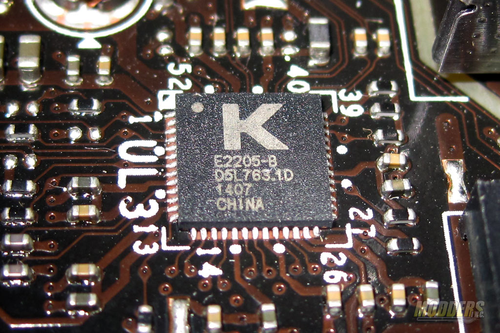
The rest of the rear-IO provides an additional pair of USB 3.0 ports (for a total of four provided natively by the B85 chipset), optical audio output, four USB 2.0 ports, a legacy PS/2 connector and four video outputs in the form of a VGA, DVI-D, HDMI and DisplayPort. Gigabit Ethernet connectivity is provided by a Qualcomm Killer E2205 NIC.
