Meshie : by Tazz
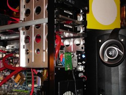
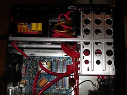 I then start the hardware installation and seeing how things are going to fit up. Seeing that I plan on only running one optical drive. I slip the hard drives in under it and make sure to leave myself enough room to mount the water pump and its circuit board. As we can see in the first photo, I was able to achieve this with no problem. I then start in on the wiring and plumbing of the water lines.
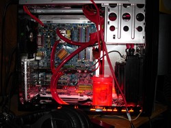
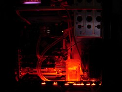 With the essentials installed I start playing with the lighting at this point. I plan to use led accent lights on this mod rather than using any CCFL’s.
 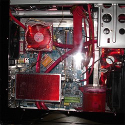 I then decided to add more red into the picture. I paint the side fan grills with some Metalcast red paint from Dupli-Color. This paint kind of gives you an anodized look on the parts.
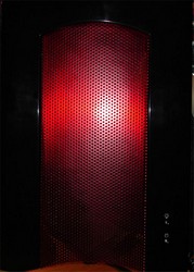
 I then applied the same paint to the rest of the exterior parts.
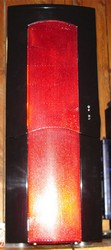
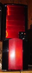 Everything is starting to come together at this point. The painting process does give the mesh a nice red look and should give me a unique look.
 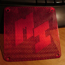 I had to add a little color to the rear of the case as well :D.
 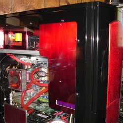 The next step required fitting the Matrix Orbital screen it a new optical drive cover plate. I simply added a little extra length to the height of the stock plate to get enough room to mount the Martrix Orbital screen.
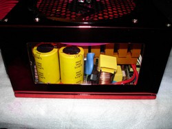
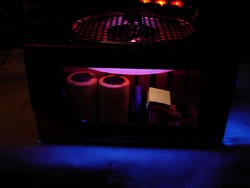 I then move on to addressing the lighting issue in the PSU that we worked on earlier. Doing something like this is fairly simple, but keep in mind that you must void your warranty to do it.
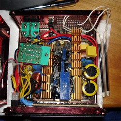
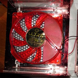 I pull the cover off the Red X2 and disconnect the lights and fan so that I can get the upper cover out of the way.
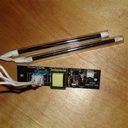
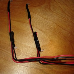 At this point I pull the circuit board that controls the lights and make up a couple sets of wires that have two LED’s each on the ends of them.
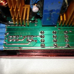
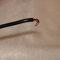
I flip the PSU up on its end so I can get a good look at the modular interface board. I plan on getting the needed power for the lighting from the backside of the modular interface. I strip off the end of the wires and put a small U shaped bend in them.
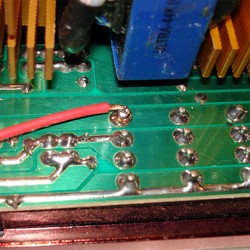
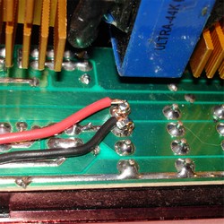 I then solder the Red wire to the +12V side of the interface and then follow up with soldering the black to the ground side. I didn’t go crazy with the solder here. I applied enough to hold my wires and not make things messy. You want to make sure that you have no solder or wires connecting with the others.
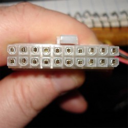
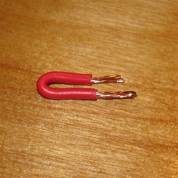 The next step is to test the lighting. The quickest way to do this is to use a small PSU tester that will make the circuit and allow you to power up the PSU. I simply jumper out the 3 and 4 pins with a small piece of wire.
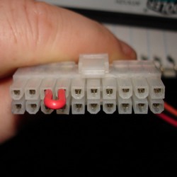
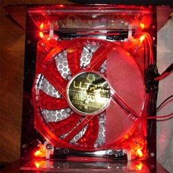 With the jumper in place we can now power up the PSU. I don’t recommend just anyone to crack open a power supply with out have basic knowledge of the components that are used with in it. Touch the wrong thing in a charged power supply and you could easily regret doing so.

