HTPC IR Receiver Guide
Making the Receiver
The basic layout of the components is fairly simple and it can be modified to suit your needs. If you do not use the same components that I used you will need to make sure you use the correct pins on each item. The pins layout is normally on the back of the package.
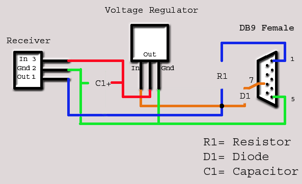
Here is how mine ended up.
The following is a cut and paste from the WinLRC site that describes how the circuit works. I suggest that you go and read the entire article here: Receivers.
�The power for the circuit comes from the RTS line of the serial port. D1 protects the circuit from the negative voltage that is usually on the RTS pin.
The LIRC driver will change the serial port settings on initialization so that the circuit will get the necessary positive voltage. For most standard PC serial ports this will be approximately 10V. IC2 will convert the input voltage to exactly 5V. As the input voltage for the 78Lxx type regulators has to be at least 2V higher than the output voltage to work reliably, this circuit probably won’t work on some notebooks. The line drivers inside notebooks often provide voltages about 6V or even less. So you should make sure that your serial port delivers at least 8V of output voltage. If your serial port provides less you can also try using a low-dropvoltage regulator (e.g. LP 2950 CZ) instead of the regulator suggested here. Low-drop types need much less voltage offset for reliable regulation. Instead of pulling the power supply from the serial port you can also use a different source like e.g. the USB port or the internal 5V line to power the circuit. Then you won’t need a voltage regulator at all.
C1 is optional but I recommend using it anyway. R1 is a pull-up that makes sure the DCD line is on a valid voltage level if the receiver does not receive anything. When an infrared signal is detected IC1 (this is true for active low receivers, if you use an active high receiver leave away R1 or make it a pull-down to GND) pulls DCD down to ground, which should already be interpreted as a logical “1” (DCD=0) by the serial port.�
Now I am not going to go step by step on how to solder this up, because some one has already done a great job doing so. See it here http://www.manoweb.com/alesan/lirc/Now this site makes the IR receivers fit entirely in the RS-32 housing. It would plug directly in to the serial port on the back of your PC. I do not know about you but the back of my PC�s always face away from me. I�m guessing that they hope the IR receiver could pick up the signal by being reflected off a wall or something. The great part about this project is that you can do it anyway you like.
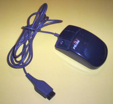
Like most of you I have lots of old non-working mice in my junk pile. I figured that I could use one for everything I needed. I could use the mouse as the case for the IR, the cable to wire it up and the plug to connect it to the PC. Of course the pin out for the mouse was totally different from what I needed to make the receive work. �HACK�, there goes the plug. The mouse was more than big enough to hold everything and I actually completed it the first time with it, but I did not like the way it looked. �HACK�, there goes the mouse. So the only thing I ended up using was just the cable. I do not see why you could not use some CAT 5 cable, this way you could make the cable as long as you want.
Using a holder as I did will make your life allot easier when trying to solider small items.
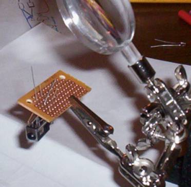
Here I am putting the IR receiver, voltage regulator and capacitor onto a piece of a PC board that I cut to size.
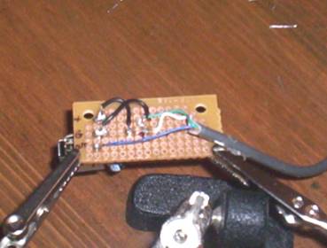
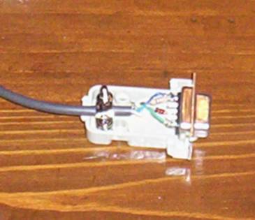
I decided to put the Resistor and Diode in the RS32 housing. Wiring it this way was a little easier for me.
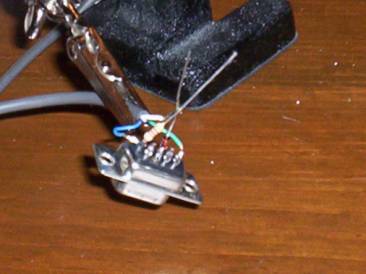
Which meant that I would have less stuff in the box to wire up and maybe some room for future mods.
