How To Get a LCD Character Screen to Work
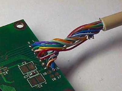
This is an example for pin 1 on the DB25 connector. Find pin1 on the DB25 connector. The pin number is normally printed somewhere on the plastic holding the pins in place. Remember the color of the wire connected to this pin (remember a wire can sometimes have two colors). Find the corresponding color wire at the LCD end of the printer cable. Solder this wire to pin 9 on the LCD. This method of connecting the wires is then continued with the rest of the pins on the table below.
DB25 connector Pin Number LCD Pin Number LCD Pin Description
1 9 Enable 1
2 8 Data 0
3 7 Data 1
4 6 Data 2
5 5 Data 3
6 4 Data 4
7 3 Data 5
8 2 Data 6
9 1 Data 7
14 10 Read/Write
16 11 RS
17 15 Enable 2
25 13 Ground
13 14 +5V

Printer port cables soldered to the LCD. You will notice that the parallel port cable has 25 wires and you will be using only 16-18 wires total. The rest will be cut short so that they are not in your way. Don’t cut these extra wires until you are finished with the soldering. Just in case you soldered the wrong wire. You will need to check each wire with the Multi-meter from the end of the wire to the DB-25 plug to make sure you have the correct wire for soldering. Once you have finished the above procedure you will find that you have a few connections that are empty. Pin 3 will be empty, it is used for contrast. There are a couple of ways to use this, 1 is to put in a POT (potentiometer) or wire it direct and not have a variable contrast. I chose not to have the variable contrast. Here is how to do both. Contrast Control Pin 3 on the LCD is used for contrast control. There are two options which can be taken in this step.
The first option which is the easiest is to fix the contrast at a certain level. This is a bit of a gamble as the contrast setting may not be to your liking, but in most cases, the LCD contrast is set at an acceptable level. To do this, simply solder a piece of wire from pin 1 to pin 3 on the LCD. If you do this, skip to the next step of this guide.
The second option is to connect a potentiometer (or “pot”) to the LCD which will allow the LCDs contrast setting to be changed.
There are two types of pot’s which can be used for this, a normal full size pot, or a “trim-pot”. I would recommend using a trim-pot, as it’s small, and if you’re clever can be mounted on the back of the LCD itself. The value of the potentiometer will need to be 10KOhms. It can be of either the “linear” or “logarithmic” variety, it won’t make a difference.
Solder a wire from the center pin of the pot, to pin 3 on the LCD module.
Solder a wire from either of the two remaining pins on the pot to pin 1 on the LCD module. Solder a wire from the remaining pin on the pot to pin 2 on the LCD module.
I didn’t have a backlight on my LCD screen but I will include how to hookup a backlight. Backlight Control Two components will be needed for this step, a resistor of a value you’ll have to calculate, and a 100ohm potentiometer or trim-pot. The resistors value will need to be calculated first. To do this, you will need the LCD’s specifications which should be available from the manufacturer of the LCD module. You’ll need to know the recommended voltage required for the backlight and the current.
Then using the following calculation, work out the resistor value needed:
R = (5 – volts) / current For example, if your LCD required 4.2V at 400mA it would work out to be: R = (5 – 4.2) / 0.4 which makes R=22.5ohms If you cannot work out what the current is in decimal, use the following as a guide: 350mA=0.35, 100mA=0.1, 50mA=0.05, 10mA=0.01, etc.
Now, solder one lead of the value resistor you calculated to the center pin of the potentiometer or trim-pot.
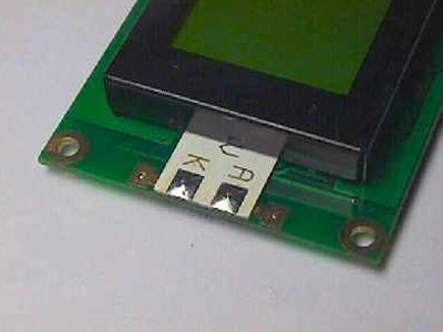
You’ll now need to identify the connection points on the LCD for the backlight supply. If the LCD has 16 pins together, then the 2 unused pins should supply the backlight. They should also be labeled, if not, check the manufacturers data-sheet for the LCD. If the LCD does not have 16 pins together the connector pins for the backlight should be located at one of the ends of the LCD. The pins are normally labeled “A” and “K” or possibly “+” and “-“.
Now solder a wire from the “K” or “-” backlight supply pin, to pin1 on the LCD.
Solder one lead of the value resistor you calculated earlier to the center pin of the potentiometer or trim-pot. Solder a wire from pin2 of the LCD to the other remaining lead of the resistor.
Solder a wire from either of the two remaining pins on the potentiometer or trim-pot to the “A” or “+” backlight supply pin.

A typical LCD backlight wiring point.
Next is to setup the project with the 5 volt power. The explanation that I’m using is for the Molex connector but a USB plug can be used. You’ll need to find which wire on the USB plug is for ground and for 5 volt power. I’m not showing how to do this because I didn’t use it so I don’t have it available at this time. Here is how to do the Molex.
Power
To power the LCD and the LCD’s backlight, the DB25 connector end of the cable will now need to be modified. You will need to obtain a male “molex” connector. If possible, with wire already attached to it.
A molex connector is the style of connector that is used to connect the power to hard-drives and cdrom-drives in your PC.
Male molex connectors can be difficult to find, large electronics shops should stock them as well as some PC repair shops. Another source of male molex connectors is some brands of CPU fans.
Solder a moderately long piece of black wire from pin 24 of the DB25 connector.
Cut the wire on pin 13 as close as possible to the DB25 connector then strip the end of that wire. Solder a red wire (same length as the black), to the wire that was just cut from pin 13 and insulate it with insulation tape or heat-shrink tubing.
You now must make 100% sure you get the next few instructions right. If you do not, there is a big chance you’ll destroy the LCD module and possibly some of your PC’s hardware.
Use the next image to identify the 5V and ground connectors on the male molex connector.


Nice, but this parallel port is so 90s. Not many modern mobos (and by that, I mean Core2 LGA775 and newer) still have one, and why bother, if you can get an Arduino (they were already available and popular in 2012), add an LCD shield, then connect this directly to the mobo via one of the USB ports?
I think this was from an archive post in 2007. The date was just marked as 2012 when the server moved.
You are correct Ron, this was an old post that was imported into the new theme in 2012. Krzysztof Słychań would be cool if you could do a how to on this and we can share it.