How To Get a LCD Character Screen to Work
Extra Parts That Help
Helping Hands (project holder)

Magnifying Glass (to check connections up close)
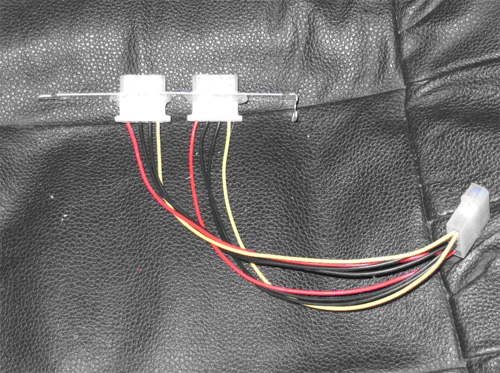
External Molex connection 
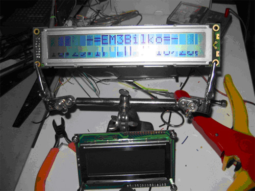
I purchased my LCD screen from an online vendor, www.shopeio.com, they have a wide selection and the prices are good. They ship by way of the USPS only, so there will be no tracking number, and it could be slow about arriving. I have ordered 3 screens from them and I think I screwed up the first one but the second and third worked. However the third one only worked on the top line only the second line gave only the bottom half of the character. I think it came from the manufacture that way and has nothing to do with Shopeio. The parallel printer cable was from my junk drawer. Since most printers now use the USB port finding an older parallel port cable shouldn’t be a problem. The molex connector was also from my junk drawer. You can find them on old fans that don’t work any more or some fans come with a molex and a 3-pin connector for plugging into the motherboard. With this type just cut off the molex and the fan will be just fine working with the motherboard. The reason that I went with the molex was to be able to obtain power without having to run the cable out the back of the case to plug into a USB port. Now you’re wondering, what is the different between the power connector and the printer cable? Some motherboards don’t have a parallel port but have a header to plug a bracket onto and then fix it onto a PCI slot. That is what I have in my case; it could be different for each motherboard. The software was actually the easiest part of collecting the materials, just downloaded the program from the selected sites. The schematic was the hardest part. Being that there are different wiring diagrams a person doesn’t know which one will work with the LCD that you purchase. All you have to go by is the amount of connections, which ranges from 16-18 connections. The first LCD I used had 18 connections and the last 2 are for the backlight. If you have 16 connections then there is no backlight. My other 2 LCD’s only had 16 connections and they didn’t have backlights. A LCD that has18 connections may have 2 different configurations, you could have all 18 connections in a line or 16 connections in a line and 2 at the end of the LCD. The 2 extra connections are for a backlight. I got the working schematic from CrystanFonts and there are 2 different setups, 1 for a 4×40 character screen and one for a generic character screen. I used the generic version because I had a 2×20 LCD screen. Here is the explanation that I used for wiring my LCD.
This is the difficult bit of the project and will be the most frustrating. Take your time, and get it right the first time.
The easiest way to describe how to connect the wires, is to give an example.


Nice, but this parallel port is so 90s. Not many modern mobos (and by that, I mean Core2 LGA775 and newer) still have one, and why bother, if you can get an Arduino (they were already available and popular in 2012), add an LCD shield, then connect this directly to the mobo via one of the USB ports?
I think this was from an archive post in 2007. The date was just marked as 2012 when the server moved.
You are correct Ron, this was an old post that was imported into the new theme in 2012. Krzysztof Słychań would be cool if you could do a how to on this and we can share it.