Gigabyte Z97-D3H Motherboard Review
A Closer Look at the Gigabyte Z97-D3H Motherboard Motherboard
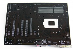
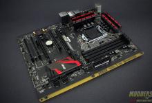
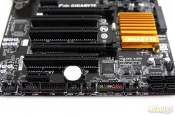
The Gigabyte Z97-D3H is slimmer than the standard ATX motherboard with only a width of 214 instead of 244mm and has a golden (surprise, surprise) heatsink color scheme. Thankfully, the slots and ports onboard are mostly gray and black.
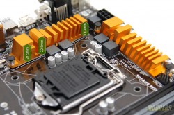
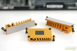
The VR heatsinks are small with a simple airflow friendly design held in place by push-pins. Underneath the heatsinks are thermal pads for the CPU PWM controller and MOSFETs. The Z97 chipset heatsink also uses push-pin locks but the insulation is a much thinner thermal tape.
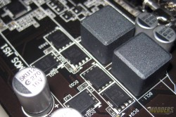
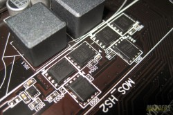
With the VR heatsinks removed, the CPU power system shows a 4-phase design using an Intersil ISL95820 PWM controller and Vishay SiRA12DP PowerPAK SO-8 MOSFETs. The ISL95820 has three integrated drivers built-in, so an additional ISL6625ACRZ-T driver is used for the SiRA12DP MOSFETs arranged with one on the high-side and two for the low-side on each phase. There are also four x 600nH ferrite chokes and six x 560uF 5K-rated AP-Con output capacitors.
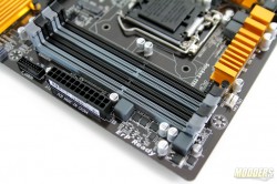
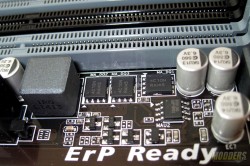
The 8-pin CPU power is located at the very top edge with the locking latch facing upward. Memory power uses a single-phase Richtek RT8120 with three ON-Semi NTMFS4C10 power MOSFETs (one high, two low) and 1uH ferrite inductor. The DIMM slots support up to 32GB of DDR3 and up to 2933MHz (UEFI memory multiplier as of F7 BIOS).
There are five 4-pin fan headers in total assisted by four Nuvoton 3941S-A linear fan drivers with built-in short circuit current limit protection and over temperature protection.
Along the right edge is the essential 24-pin power for the power supply, a 19-pin USB 3.0 header right below it and two angled SATA ports that is also able to function as a SATA Express port. All the USB 3.0 and SATA ports provided by the Z97-D3H are from the Intel Z97 chipset.
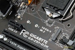
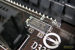
An M.2 SSD port is also provided between the expansion slots and the CPU socket. Users can choose to either use the M.2 SSD port or the SATA Express port and users can also just use any of the two SATA ports of the SATA Express port as a regular SATA. The limitation is that only one of these may be used at the same time so if the M.2 SSD slot is populated the angled SATA ports will not work for SATA or SATA Express. An ASMedia ASM1480 chip is used to switch between these functions.
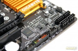
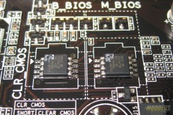
Four more SATA3 ports from the Z97 chipset is provided at the bottom edge. Two BIOS chips are also visible here as Gigabyte’s redundant BIOS protection scheme. If one is corrupted, the secondary BIOS chip kicks in automatically so there is minimal down-time.
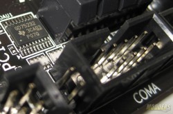
The front-panel connector headers are all color coded and clearly marked for convenience at the bottom edge, sitting along with three USB 2.0 ports provided by the Z97 chipset, a 19-pin Trusted Platform Module header, and a COM port via a Texas Instrument GD75232 Serial-UART interconnect chip.
Expansion slot distribution is as follows (in order left to right):
- PCI-E 2.0 x1
- PCI-E 3.0 x16 (from Haswell CPU)
- PCI Slot
- PCI Slot
- PCI-E 2.0 x4 (from Z97 Chipset)
- PCI slot
- PCI-E 2.0 x1
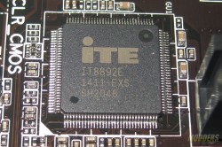
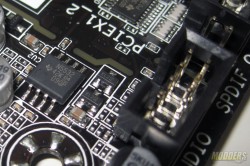
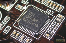
The PCI-E 2.0 bandwidth from the Z97 chip is shared between the x4 slot and the two PCI-E 2.0 x1 slot and switching duties for this function is handled by an ASMedia 1440 switch. Users can choose to use either the PCI-E 2.0 x4 slot or the two PCI-E 2.0 x1 slots. CrossFire is supported but NVIDIA SLI does not run on PCI-E 2.0 x4 plus the motherboard has to be NVIDIA SLI Certified (licensed with additional cost) before it can run dual NVIDIA cards. An ITE 8892E bridge chip on the other hand takes up one available PCI-E 2.0 x1 from the Z97 chipset and provides three legacy PCI slots. An SPDIF header is also available between the COM port header and the front-panel HD Audio header.
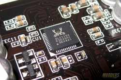
The audio subsystem is physically isolated from the rest of the PCB to minimize interference but the Realtek ALC1150 HD Audio codec is not shielded unlike Gigabyte’s higher-end motherboards nor does the isolated area light up. A Texas Instrument N5532 amplifier is also used for the front panel audio header.
In the rear I/O, a pair of USB 2.0 ports and four USB 3.0 ports from the Z97 chipset are available. Six analog audio outputs are also provided.
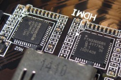
The rear PS2 port is provided by an ITE8620E Super IO chip which also handles system and temperature monitoring functions. An Intel i217-V provides Gigabit Ethernet functionality while two separate level shifters (ASMedia 1442K and NXP PTN3360DBS) handle switching duties for the rear VGA(max 1920×1200@60Hz), DVI-D (max 1920×1200@60Hz), and HDMI 1.4a (max 4096×2160@24Hz) display outputs.











Thank you very much :D