Gigabyte Z170X-Ultra Gaming Review: Rebel Without a Pause
A Closer Look at the Gigabyte Z170X-Ultra Gaming Motherboard
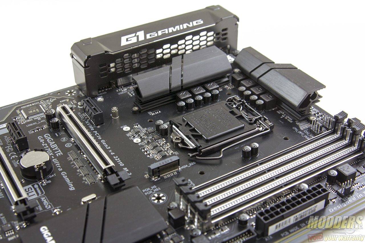
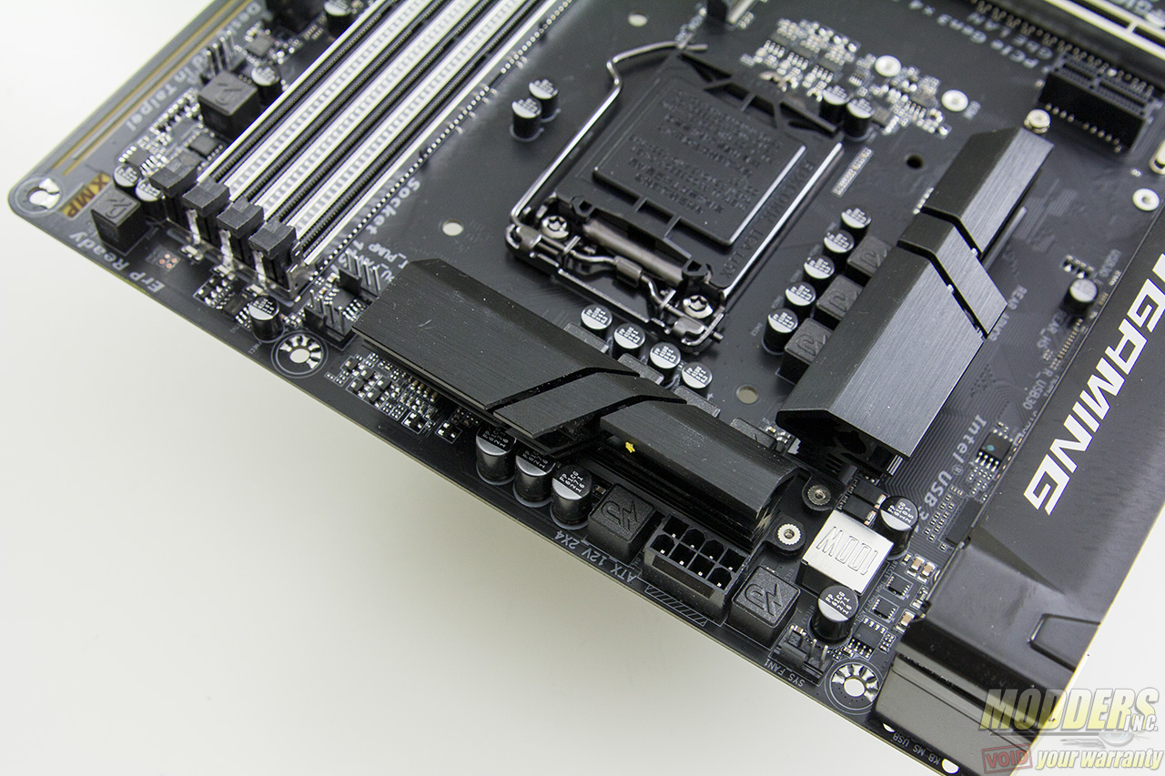
Like the Z170X-Gaming 7, an IO cover comes pre-installed, but this one is more airflow friendly with honeycomb perforations so hot air can pass through. The IO shield also has ventilation on it so this basically just gives more room for hot air from the inductors and VRM to flow out of instead of getting trapped in a much smaller area.
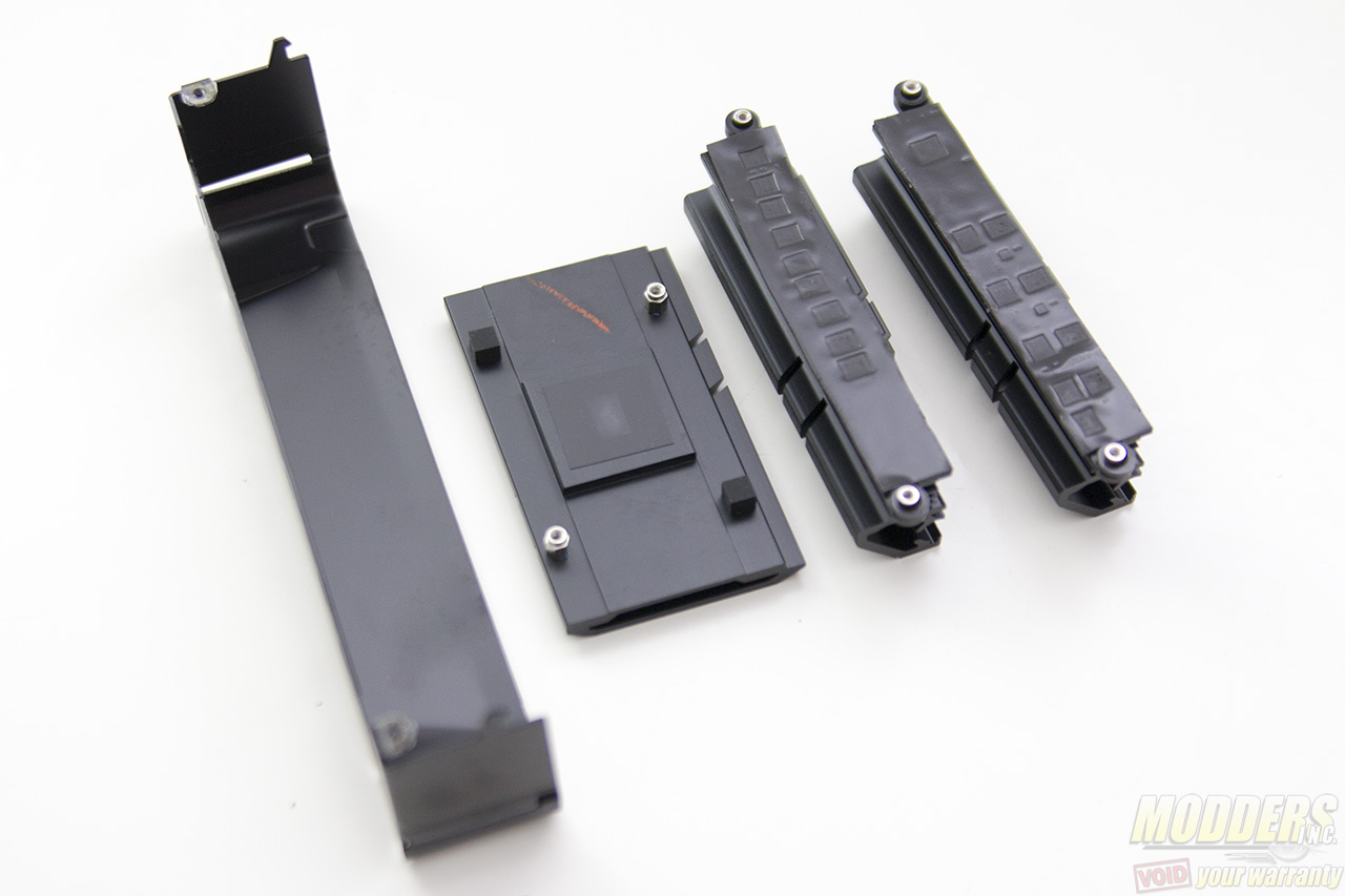
The VRM heatsinks themselves are not substantial by any means, nor do they have a heatpipe distribution like in the previously reviewed Z170X-UD5. The MOSFET blocks weigh 48 grams each while the chipset heatsink clocks in at 42 grams. The heaviest is the IO cover which weighs almost twice as much at 70 grams. All are secured with screws at the back (with the chipset heatsink screws having springs for distributed tension). Since they are all black and single-piece units, modding and repainting is straightforward and very easy.
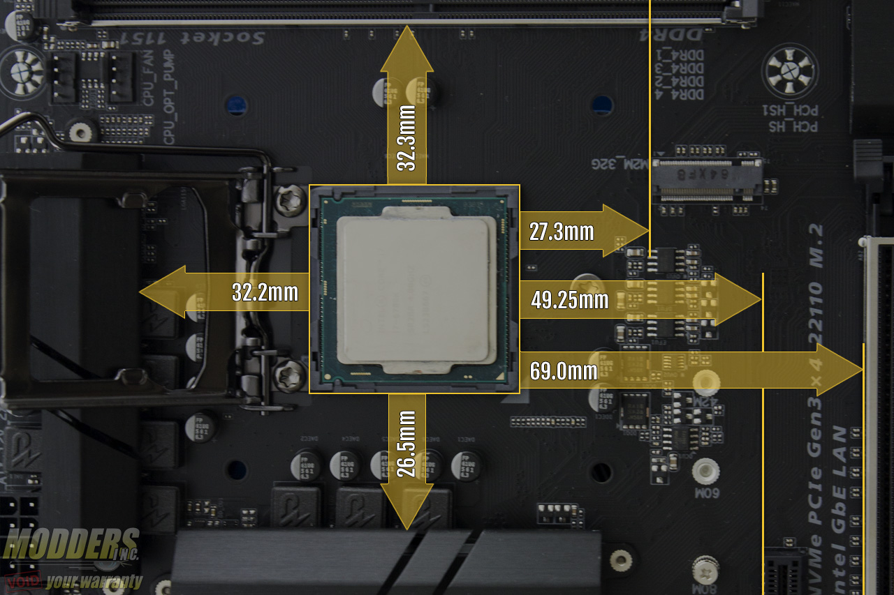
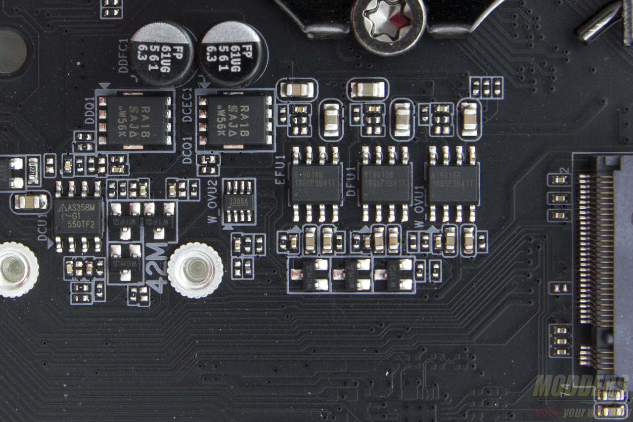
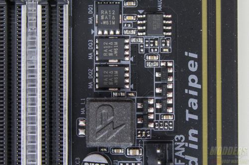
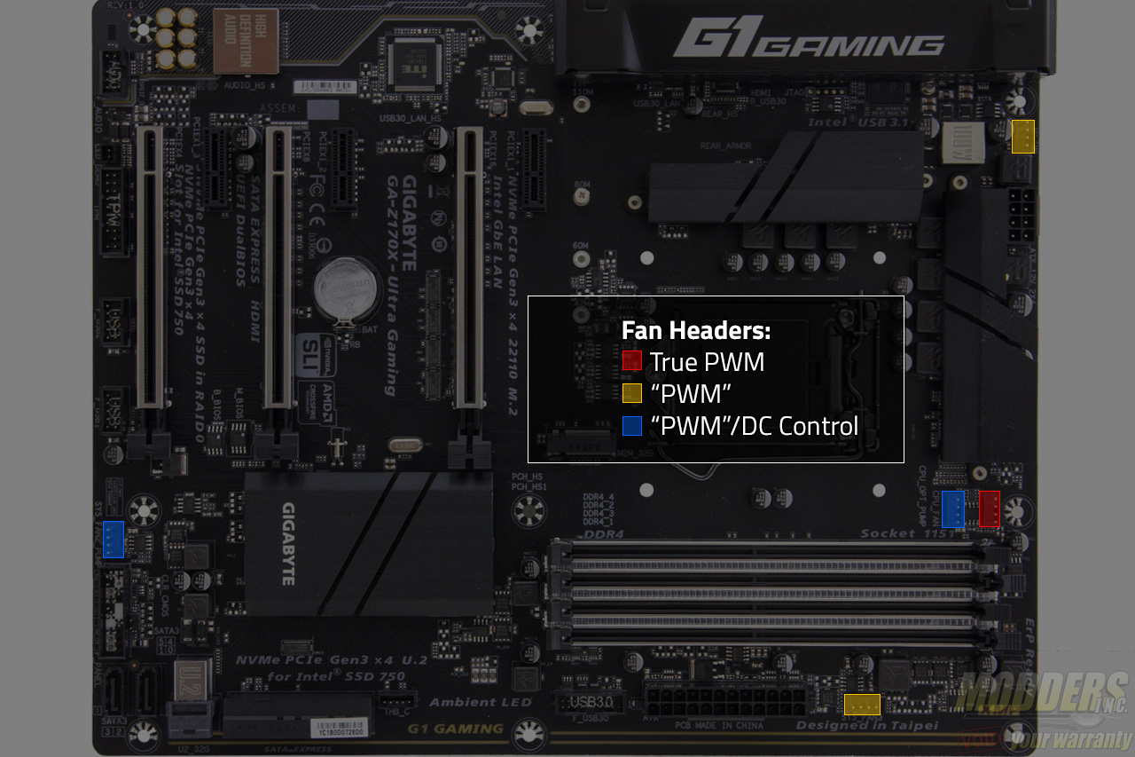
Space is very generous for the RAM clearance at 32.3mm compared to 27mm or under. The M.2 slot is directly right above the top-most PCI-E x1 slot and below the CPU socket where the linear regulartors and MOSFETs for the minor CPU rails are. Gigabyte uses a ASM358M-G1 linear regulator with a SiRA18DP Trenchfet and there is a bank of Richtek RT9018B LDOs. These components do not heat up to a critical degree so thermal problems are of no concern for M.2 devices here. The CPU and CPU_OPT 4-pin fan headers are located at the top between the CPU socket and DIMM slot.
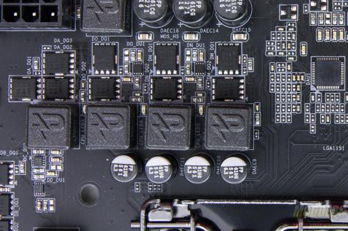
The main PWM controller is an Intersil ISL95856, a dual-output 4+3 phase capable IMVP8 controller from Intersil for the CPU+GT.There are three integrated drivers in total on this controller, two of which are on one output (voltage regulator A) while the third one is can be used on the voltage regulator that can be configured up to three phases. All of these drivers are used and additional Intersil ISL6625A drivers are utilized to drive Vishay SiRA18DP and SiRA12DP TrenchFETs per phase. Output filter has custom 500nH inductors with 561uF Japanese FP caps.
The 8-pin EPS12V CPU power connector is at the top right corner, tightly squeezed right above the VRM heatsink and flanked by two chokes. Gigabyte was wise to make the latch for this power connector facing upward so it is easier to release later during uninstallation. A 4-pin fan header can be found here as well which is very convenient for rear placed exhaust fans.
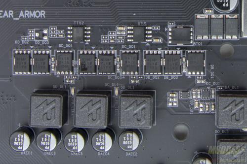
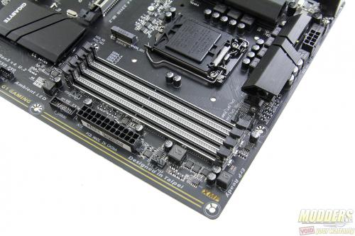
LEDs lineup between each DIMM slot, and the metal “armor” around them accentuate their brightness further once turned on because of the reflection. The DIMM slots only lock on the top end part while the bottom part is fixed. A Richtek RT8120D is used for the memory VRM with three SiRA12DP FETs, a 561uF FP cap and a 1KnH choke. Another 4-pin fan header is located here, right above the 24-pin connector.
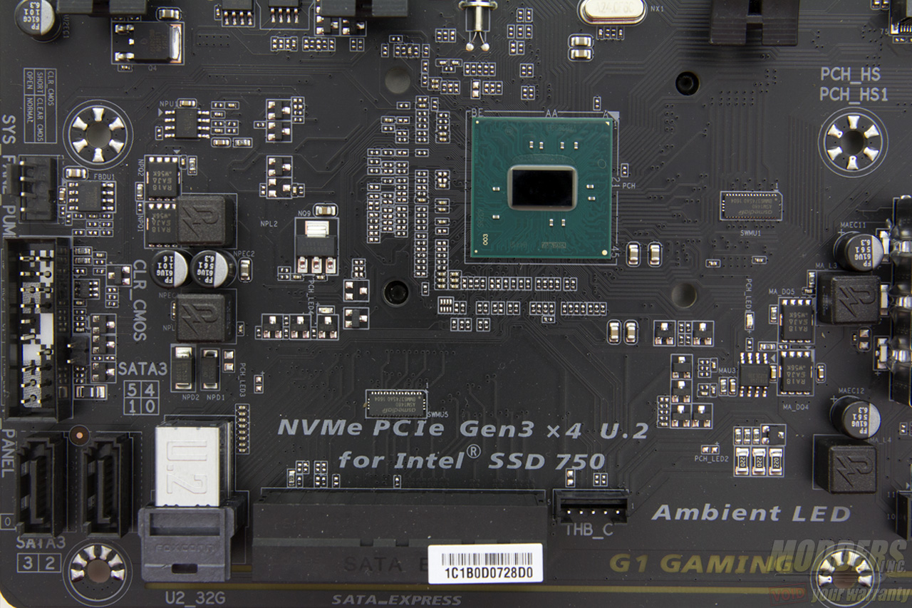
Onboard storage begins with a 19-pin USB 3.0 header right below the 24-pin power supply connector. This is natively from the chipset. There is also a thunderbolt connector header available for a Thunderbolt add-in card.
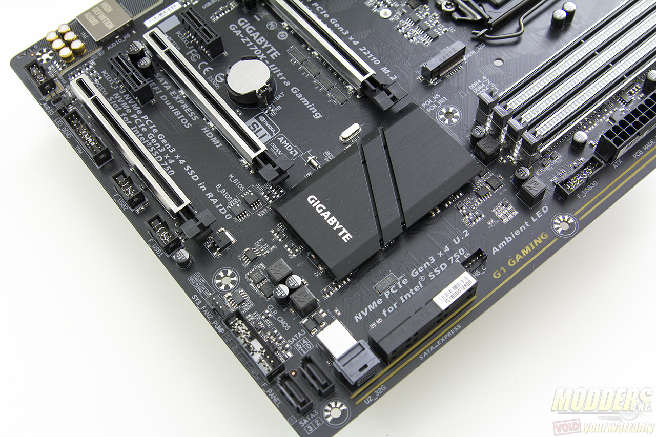
Provided are six SATA3 headers, two pairs of are angled which can be used as SATA Express, although do not hold your breath for any SATA Express devices any time soon. What is exciting however is the inclusion of an embedded U.2 connector.
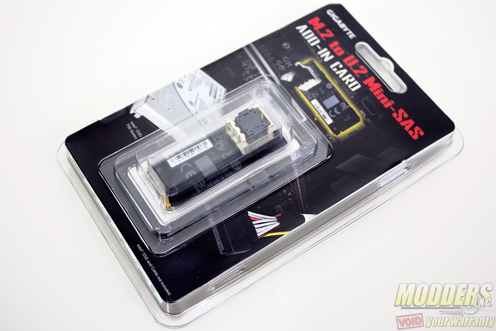
One m.2 slot is located right below the CPU socket which can also be used with an m.2 to U.2 Mini-SAS add-in card. It can be plugged into one of these m.2 slots and be able to run up to three NVMe SSDs in RAID 0 (M.2 or M.2 with U.2 converter + U.2 + PCI-E). The m.2 slot supports devices up to 110mm in length.
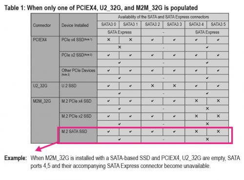
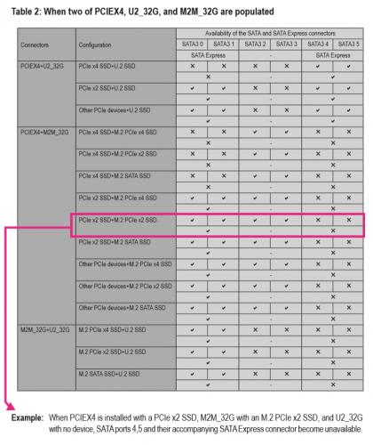
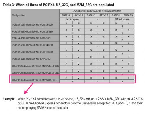
The Z170 chipset is very flexible when it comes to accommodating storage and it can actually support the three Gen 3 x4 SSD devices using switches. Gigabyte provides the following configuration for the internal storage:
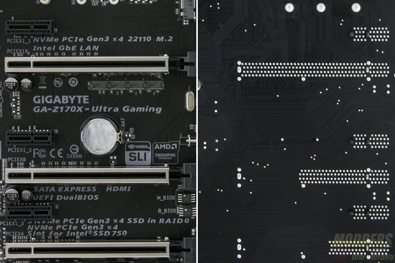
If a drive is installed on the bottom-most PCI-E slot, SATA ports 0 and 1 are disabled, using ASMedia ASM1480 switches to toggle (two are on the top side and one more is at the back) . Even if it isn’t an SSD installed here, as long as this slot is populated, SATA ports 0 and 1 are disabled. You can see that Gigabyte has prioritized the storage plexing so that it has as little interference to the rest of the lane allocation besides the SATA ports.
The last of the fan header is located right beside the front panel header on the bottom right corner. Despite all being 4-pin headers, they are not all the same. Only the CPU is a “true” PWM header with a GND, +12V, Sense and Speed control pin layout while the SYS_FAN1 and SYS_FAN3 have GND, Speed Control, Sense, VCC pin layout. There are no 3-pin DC control options available for the other headers except for the CPU_OPT_PUMP and SYS_FAN2_PUMP headers which have a GND, Speed Control, Sense, Speed Control pinout. Connecting fans in these headers allow for voltage control adjustment via UEFI.
Along the bottom right corner is the front panel header but this should be very easy to spot considering it is marked with the polarity and color coded in black and white. The G-connector accessory also makes installation easy. The clear CMOS header right above this front panel header bank. Gigabyte includes a pair of Macronix 128-Mbit flash ICs for the BIOS for redundancy. Users cannot manually switch between each but the backup will kick in automatically if necessary.
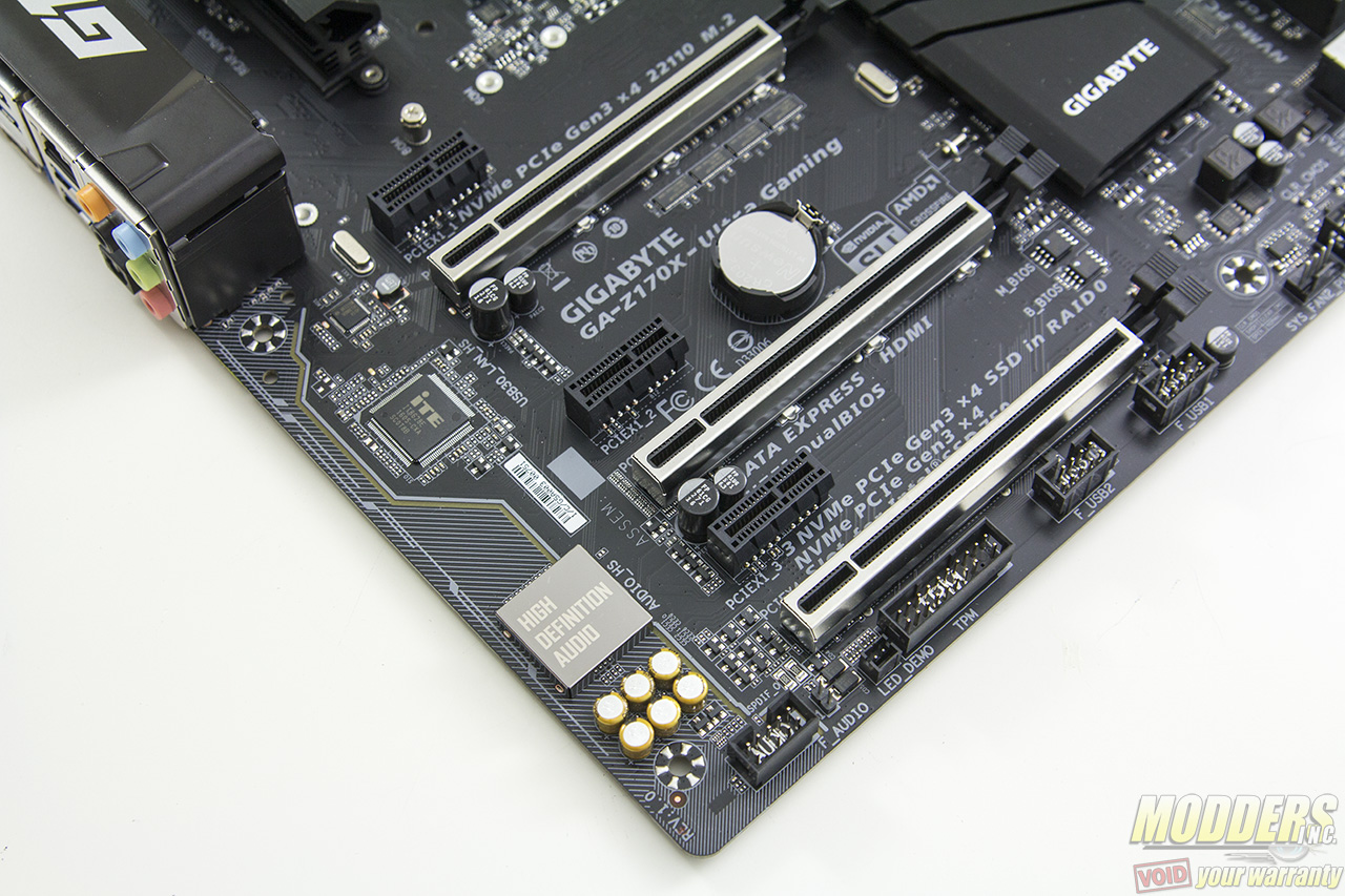
Expansion slot distribution is as follows (in order top to bottom):
- PCI-E 3.0 x1 via Z170
- PCI-E 3.0 x16 via CPU (x16, x8 when slot 4 is populated, switched by ASMedia ASM1480’s)
- PCI-E 3.0 x1 via Z170
- PCI-E 3.0 x16 via CPU (x8)
- PCI-E 3.0 x1 via Z170
- PCI-E 3.0 x16 via Z170 (x4, shares bandwidth with SATA 0, 1)
Like the G1 gaming line, the Z170X-Ultra Gaming motherboard’s PCI-E retention slots are reinforced with soldered-through shielding. This protects the motherboard and unlike what most people think, it does not prevent your video card from sagging. What this does is prevent your motherboard from getting damaged just in case something heavy drops on your video card that dislodges it. Heavy cards will sag regardless because the video card PCB is bending. If you have a video card that is actually that heavy it should include support accessories or if not, the manufacturers of it should be called out for such ridiculous oversight.
The rest of the headers along the bottom include a pair of 9-pin USB 2.0 headers, a trusted platform module header and front panel audio.
The audio subsystem is physically isolated from the rest of the PCB and audio is handled by a Realtek ALC892 HD Audio codec hidden underneath the soldered “High Definition Audio” cover. Unlike the more popularly used ALC1150 which has 115dB front DAC and 96DB DAC for the rest of the channels, the ALC892 is a bit of a downgrade with 95dB DACs. Unlike the ALC1150 which has 24-bit playback/line in, the ALC892 supports up to 24-bit playback but only 16-bit recording. This audio subsystem lights up with red LEDs (lined up at the rear of the PCB) that shine through the isolation border. Nippon Chemicon audio capacitors are used for filtering in this area and there are no amplifiers present unlike other G1 gaming motherboards.
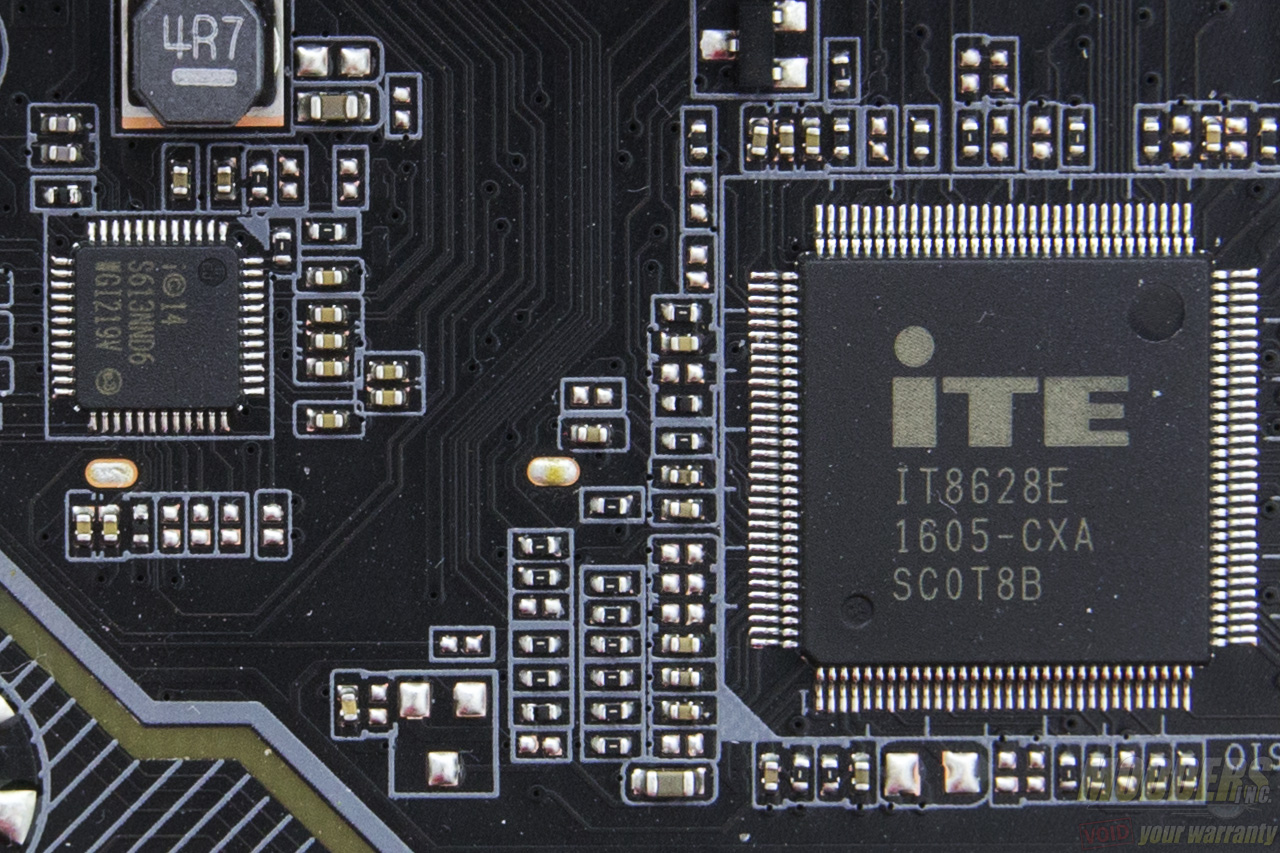
The rear PS2 port is provided by an ITE8628E Super IO chip which also handles system and temperature monitoring functions. Gigabit Ethernet is using Intel’s latest “Jacksonville” i219-V PHY.
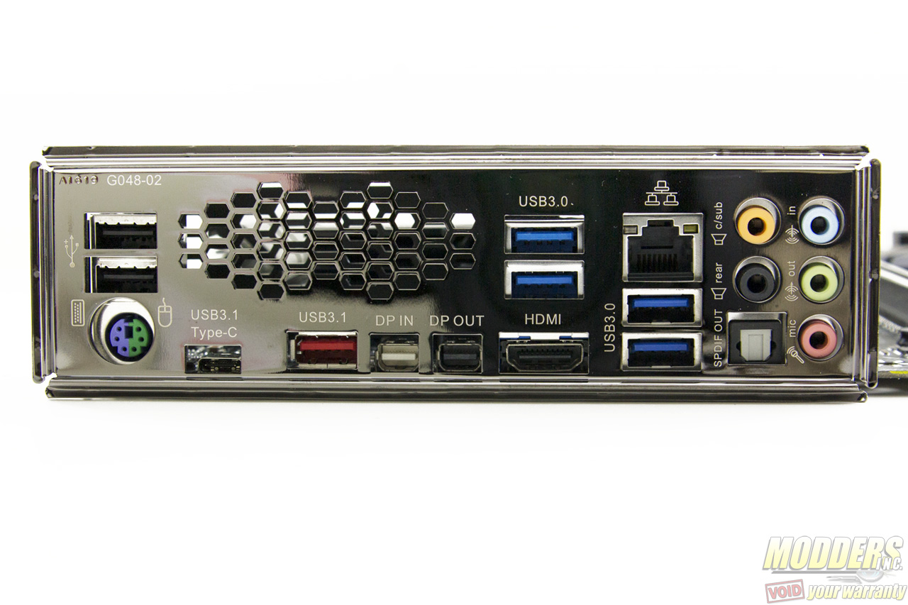
There is a DisplayPort 1.2 (Maximum resolution supported is 4096×2304@60Hz and an HDMI port supporting 4096 x 2160 @ 24Hz. Unlike the Z170X-Gaming 7, the Z170X-Ultra Gaming’s HDMI port only supports HDMI 1.2 as opposed to HDMI 2.0 since there is no Megachips MCDP2800BB present. The Gigabyte Z170X-Ultra Gaming is also very unique in that it has a DisplayPort input connector which allows for daisy chaining. For rear audio, there are five configurable analog audio jacks with one optical audio out.
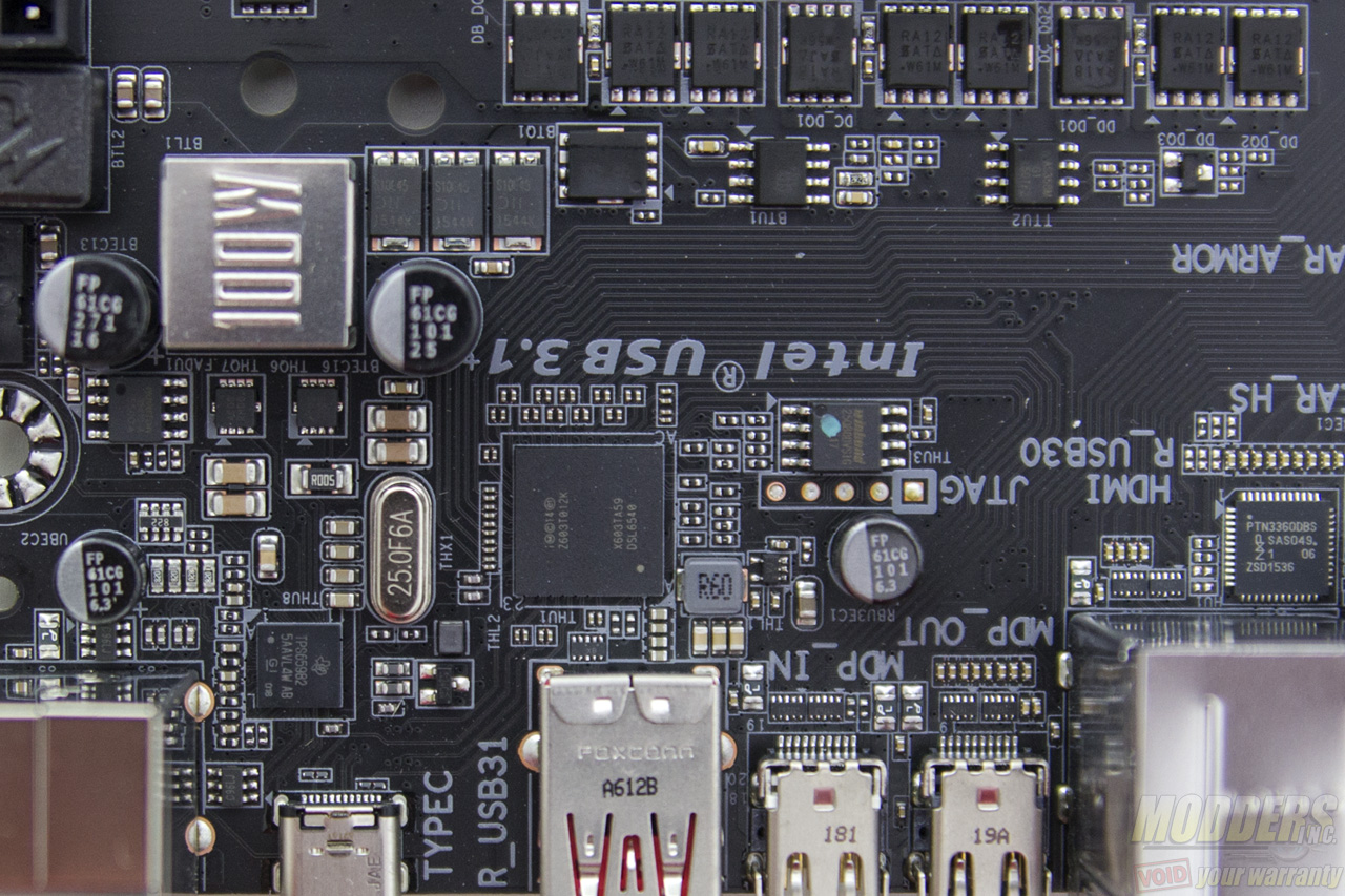
Four USB 3.0 ports are available via the Z170 chipset. Two USB 3.1 ports are provided, one is Type-A and one is Type-C via Intel Thunderbolt 3 DSL6540 controller with a Texas Instrument TPS65982 switch. This setup implemented in the circuit can provide 20v x 5A on the USB 3.1 ports (Gigabyte hides some of these components under the 100W cover near the 8-pin EPS header).



I just got these board to change my hero crappy 8 sorry. nice board. I have a lot of question one is fan header PWM data. if i have a AIO (Capt 360) the pump goes to CPU OP / pump and the fans to CPUfan for the AIO. I have a 3 pin to the rear and 2 front PWM. one on 3 and 2 (pump dc control) these is ok? or I have to make some adjustment. since I want to get a fan hub to put the front in one so i can connect direct to 12volt. your article is clear, but i am not a savvy guy for these. Any help or links will be great top get point on the right purchase direction and knowledge!!! thanks guys
Hi Carlos, sorry I didn’t see this comment earlier. For AIO pumps, it is recommended to run them at full speed (12V). The 3-pin fan is the one you put on the DC control since 3-pin fan speed can only be lowered by undervolting them. The 4-pin PWM of course you put in PWM fan headers and run it with the preset you want. Putting them in a hub, will make them all run at full speed (12V). If you have a 360 so I’m guessing you have 3 fans plus two intake for case and one more for exhaust (6 fans total?). The lowest cost option that I can see is to just get a fan splitter cable for the two front intake fans (so they can share one header) and/or use a molex to fan header adapter to fan connector plug the AIO pump and whatever fan you want to run full speed. There are 5 fan headers on the Z170X-Ultra Gaming motherboard so one two-header splitter (for the two front case intake is recommended) is enough to fit all your needs if you have six fans.
Sample of a fan header two-way splitter (can connect one header to two fans), there are cheaper options out there on Amazon and Alibaba as well: http://www.newegg.com/Product/Product.aspx?Item=9SIAABJ4666313&cm_re=fan_header_cable-_-12-162-026-_-Product
Here are some more options for splitter and/or molex-to-fan connector: http://www.newegg.com/Product/ProductList.aspx?Submit=ENE&DEPA=0&Order=BESTMATCH&Description=molex+to+fan&ignorear=0&N=-1&isNodeId=1
Some cases, CPU coolers, and power supplies also come with fan hubs for free and fan adapters so you can ask your friends if they have some, maybe they can just give you one. NZXT and Phanteks for example have fan hubs built in most of their cases.
HI Ron thanks so much for your reply. I did check all ports here testing with fans. if you still have the board. connect a jet flow or similar (as me here) to the Sys_Fan2_pump i use to test PWM and voltage. On PWM you turn off the fan and the lights still on (so there is 12v there(i do not know how to use a multimeter). on voltage regular option I put the fan in 0 and no lights no rotation. is odd. i use 4 fan to test all ports. unless there is a difference on 2000rpm in 7v or 12v is a odd. i also find other software issues. that is fantastic to expand the new trend since more and more these types of boards are more on the market that use front AIO and 2 fans on back. My idea just change since i can do that most people do, and the other is confirm that i can use. so far it is confirm that SYS_FAN1 and SYS_FAN3 are voltage regulated. So the pump can go to the CPU_OPT_PUMP.??? and the fans to the CPU_FAN??
i was thinking on something like these https://www.amazon.com/Phanteks-PWM-Fan-Controller-PH-PWHUB-01/dp/B00M0R05WE/ref=sr_1_1?ie=UTF8&qid=1479365206&sr=8-1&keywords=phantek+fan+hub OR https://www.amazon.com/SilverStone-System-Cables-Black-CPF04/dp/B00VNW556I/ref=sr_1_sc_1?ie=UTF8&qid=1479365273&sr=8-1-spell&keywords=silverstore+fan+hub
The fans where the ML120/140 or the ELOOP ones or if are 3 pin like other brands.
Yeah that Silverstone one looks good. I’m testing something on a different board right now but I could try to build on the Z170X-Ultra Gaming board next week to test out the headers again.
That is great Ron. I have search a lot regarding these PWM fan, what port do what or does not. I can say that I am almost sure that the Fan_PUMP headers are 12volts If you select on bios (F20b) PWM. Since once you restart and anter again the bios and on manual on PWM the lights of my jet flows stay on. (I can not explain) The top one monitor CPU, the one below monitor PCH. The system fan 1 and 3 is confirm voltage regulated. but still odd since, it is my understanding is not 12v, but my fans spins at max speed(my case i have jet flow) so there is 12v signal but on a different distribution. These new ways fo fans pins comes on ALL new gigabyte motherboard at least on mine, the new blue color, designare both x99 and z170, and i bet that will come on the new board on CES2017. It seams that these ways of fans and buids are a new secret. BTW SpeedFan does not work. At least on mine. I have all manufacture apps install. check also monitor software does not work correct, the only one was HWinfo64 I am changing my case and cooler soon. I can wait on your findings from your side to I can make the correct purchase.