Gigabyte Z170X-UD5 Motherboard Review: All Bases Covered
A Closer Look at the Gigabyte Z170X-UD5 Motherboard
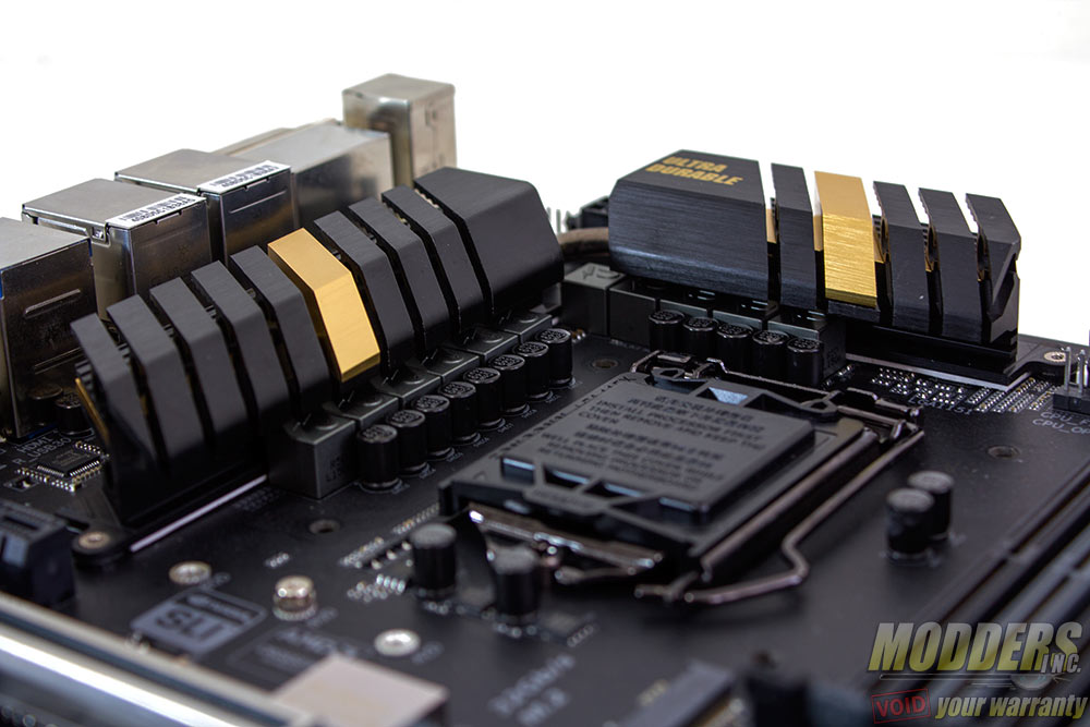
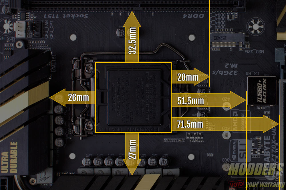
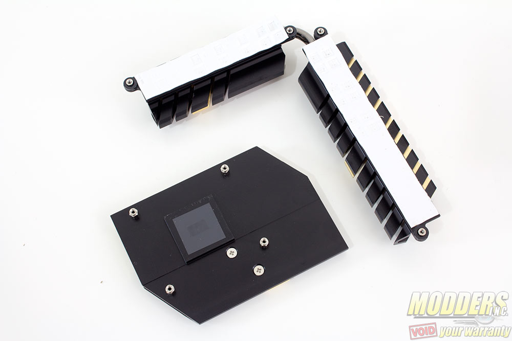
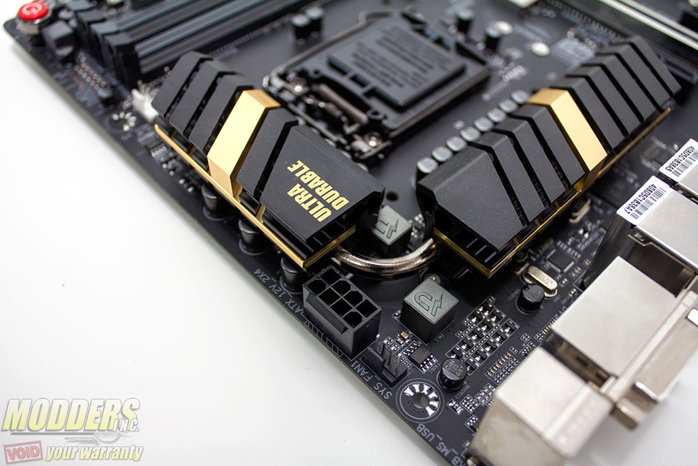
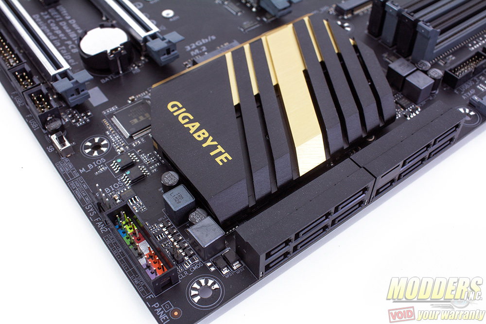
Z170 motherboards support LGA1151 CPUs but the heatsink compatibility remains the same as with LGA1150 and LGA1156 so previous generation heatsinks can be used. The two-piece VRM heatsink is connected via heatpipe in an L-shaped configuration and weighs a hefty 179 grams. The PCH heatsink weighs 101 grams on its own and all three are solid aluminum anodized black.
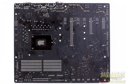
These heatsinks are secured by screws at the back. Because of the PCH heatsink size relative to the chip it is cooling, it uses spring-loaded screws unlike the MOSFET heatsinks to even out the pressure of the contact. The VRM thermal compound uses a white thermal interface material strip while the 5W TDP PCH chip uses a thin graphite pad for contact. The gold accent is held in place by screws so modders can remove this prior to re-painting.
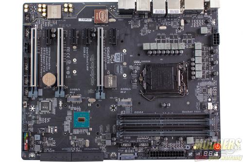
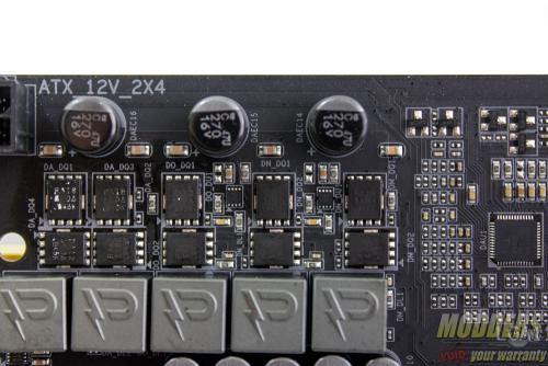
The 8-pin EPS12V CPU power connector is at the top right corner, tightly squeezed right above and beside the VRM heatsink and one fan header. Gigabyte was wise to make the latch for this power connector facing upward so it is easier to release later during uninstallation. This fan header is unusual but is a good location for the exhaust fan found on most mid-tower cases. I am surprised not more motherboard manufacturers place one in this location.
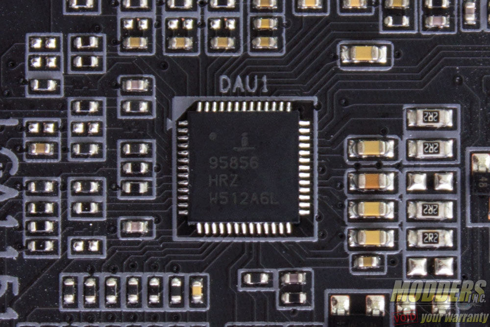
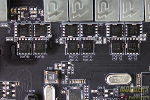
The main PWM controller is an Intersil ISL95856, a dual-output 4+3 phase capable IMVP8 controller from Intersil for the CPU+GT.There are three integrated drivers in total on this controller, two of which are on one output (voltage regulator A) while the third one is can be used on the voltage regulator that can be configured up to three phases. All of these drivers are used and additional Intersil ISL6625A drivers are utilized to drive Vishay SiRA18DP and SiRA12DP TrenchFETs per phase. Output filter has 500nH inductors with 560uF Nippon Chemicon solid Japanese capacitors.
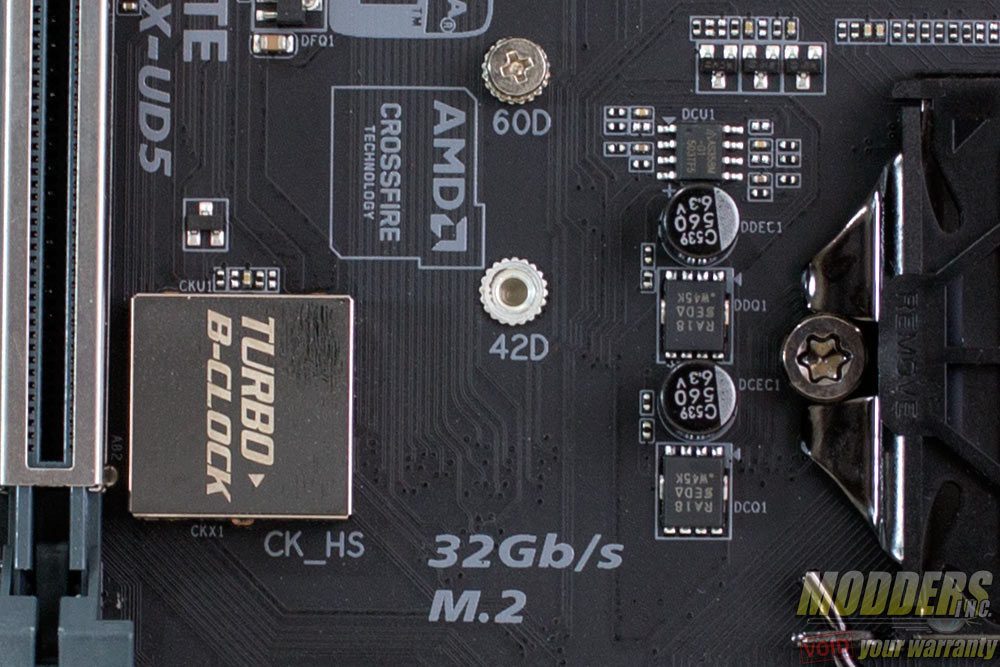
For the other minor SA and IO rails it is a lot more straightforward and simple as Gigabyte uses an ASM358M-G1 linear regulator with a SiRA18DP Trenchfet and a 560uF capacitor. This is similar to the Gigabyte Z170X-Gaming 7 motherboard as well including the presence of a “Turbo B-Clock” chip hidden underneath a soldered cover for improved BCLK OC’s.
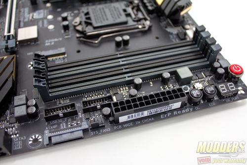
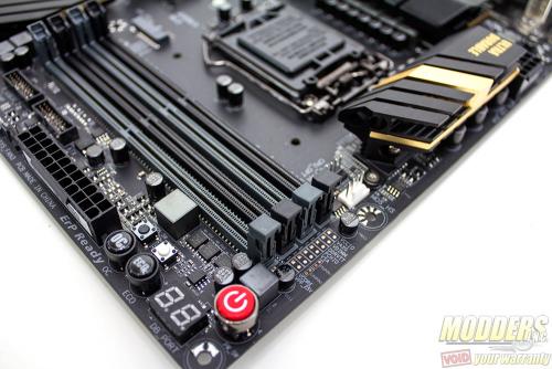
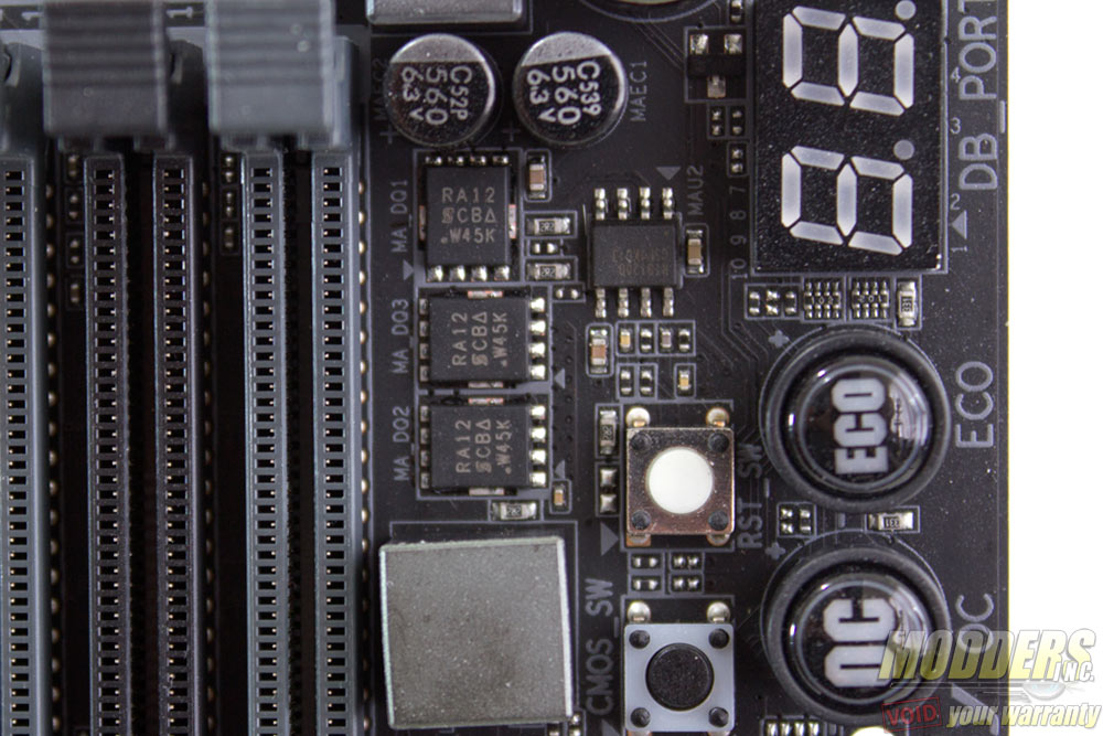
Memory VRM is handled by a Richtek RT8120D with three Vishay SiRA12DP TrenchFETs. Maximum memory capacity is 64GB with up to 4133MHz setting possible as of F5E BIOS update. At the top corner of the DIMM slots are voltage read-out points where users can point their multi-meter and measure voltages. On the top right corner are the on-board buttons and port 80 debug LED. The buttons include the power and reset buttons, as well as clear CMOS and single button shortcuts for OC and ECO mode (power mode presets).
Right below the 24-pin power are two 19-pin USB headers for dual USB 3.0 front panel output natively from the Z170 chipset. More storage options continue right beside the large chipset heatsink in the form of two M.2 slots on the left side and eight SATA ports on the right side. These SATA ports are angled and three pairs can be used as SATA Express (Switched by an ASMedia 1480 per SATA pair). The two SATA ports at the top are provided by an ASMedia ASM1061 which takes one available PCI-E x1 from the chipset. All SATA ports support RAID except for these ASM1061 SATA ports.
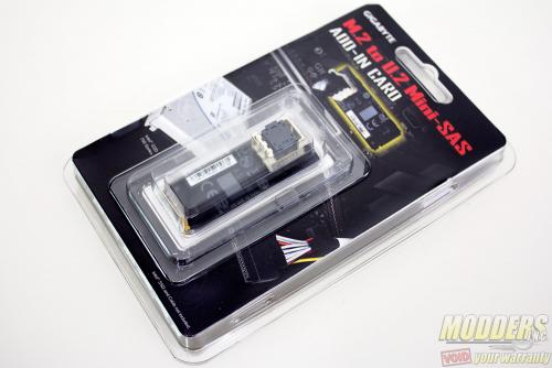
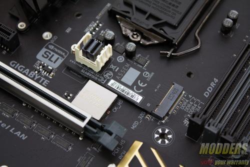
One m.2 slot is located right below the CPU socket (28mm from the socket base) while a second m.2 slot is directly beside the third PCI-E x1 slot. For U.2 connectivity, Gigabyte offers as a separate upgrade an m.2 to U.2 Mini-SAS add-in card that can be plugged into one of these m.2 slots (pictured below). So far only Intel’s 750 series SSD in 2.5 form factor supports u.2 (formerly SFF-8639) as it is fairly new but this enables users to be future proof with their setup. Besides, this is one more than any retail SATA Express option available at the time of review.
M.2 slot possible configuration (AHCI and RAID):
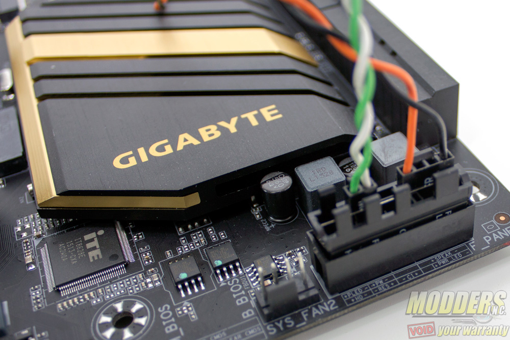
Along the bottom right corner is the front panel header but this should be very easy to spot considering it is color coded and the new accessory makes installation easy.In addition to the clear CMOS button on the top right corner, there is a clear CMOS header right above these front panel header bank.
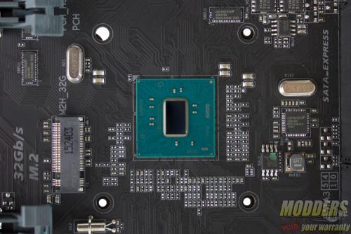
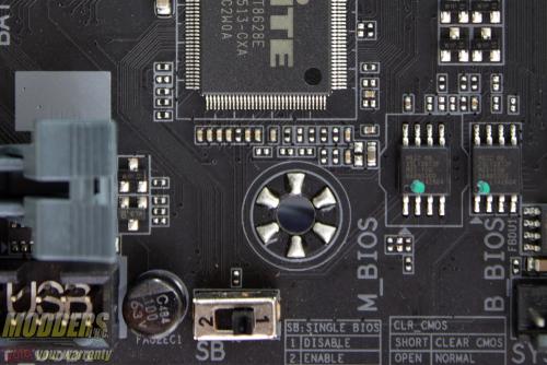
With the Z170 chipset cover lifted the ITE8628E SuperIO is now visible as well as the pair of Macronix 128-Mbit flash chips for the BIOS storage. The ITE8628E SuperIO is in charge of hardware monitoring, PS/2 and Port 80 debug LED. Gigabyte includes a pair of ICs for the BIOS for redundancy and users can actually switch between running only a single BIOS chip or both for backup.
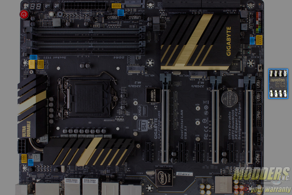
There are five PWM fan headers in total. Like in most motherboards, only the CPU 4-pin header is the “true” PWM header with Ground, Power, Sense and Speed Control (pins 1 through 4 respectively) while the rest of the headers are voltage controlled “PWM” aided by a Nuvoton 3941S each with Speed Control and Power swapping positions in pins 2 and 4.
The remaining headers at the bottom edge include two 9-pin USB 2.0 headers, a Trusted Platform Module header, Thunderbolt add-in card header and a COM port header. The two-pin S/PDIF out header is located directly on the top left of the COM port header.
Expansion slot distribution is as follows (in order top to bottom):
- PCI-E 3.0 x1 via Z170
- PCI-E 3.0 x16 via CPU (x16, x8 when slot 5 is populated, switched by ASM1480)
- PCI-E 3.0 x1 via Z170
- PCI-E 3.0 x1 via Z170
- PCI-E 3.0 x16 via CPU (x8)
- PCI-E 3.0 x1 via Z170
- PCI-E 3.0 x16 via Z170 (x4, shares bandwidth with second M.2 slot)
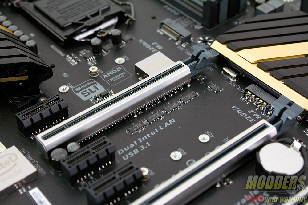
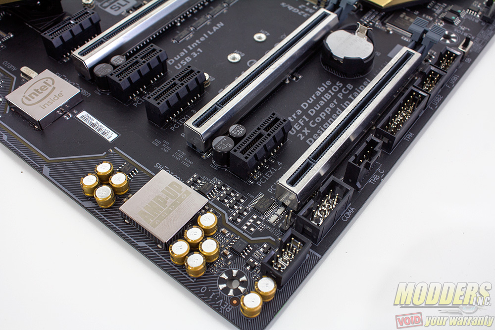
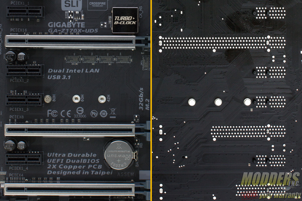
Additional PCI-E power can be fed via a SATA power connector on the side of the motherboard, useful for when overclocking PCI-E video cards. Like the G1 gaming line, the Z170X-UD5’s PCI-E retention slots are reinforced with soldered through shielding. This protects the motherboard and unlike what most people think, it does not prevent your video card from sagging. What this does is prevent your motherboard from getting damaged just in case something heavy drops on your video card that dislodges it. Heavy cards will sag regardless because the video card PCB is bending. If you have a video card that is actually that heavy it should include support accessories or if not, the manufacturers of it should be called out for such ridiculous oversight.
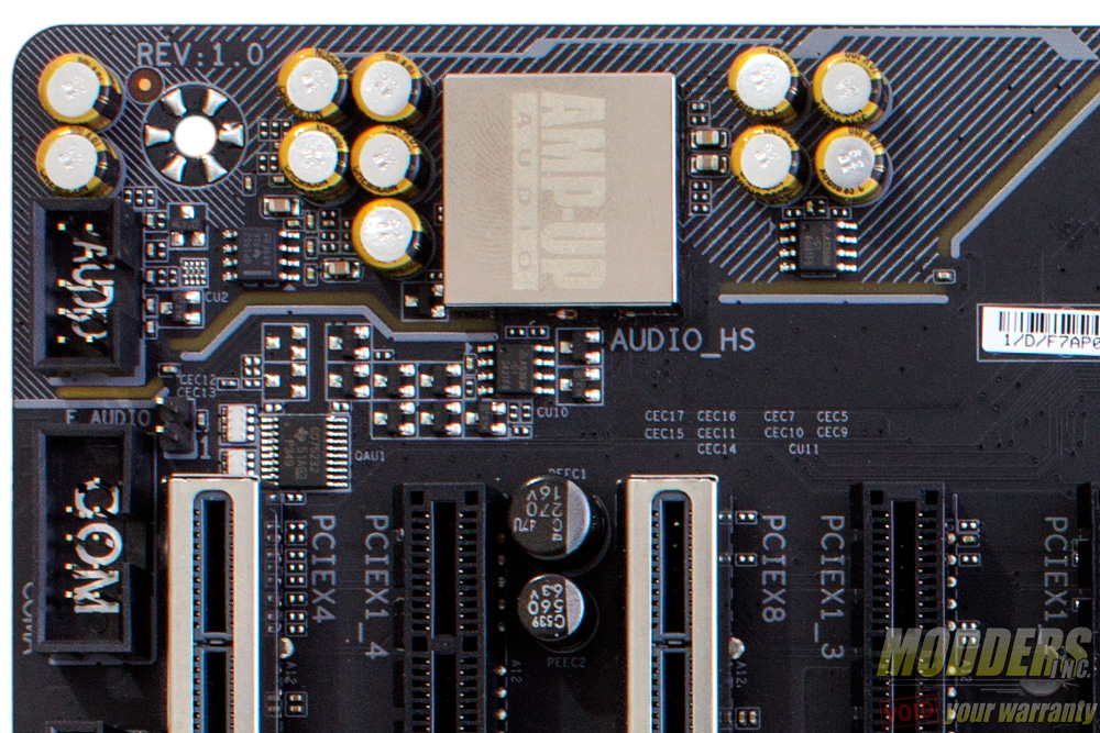
The audio subsystem is physically isolated from the rest of the PCB to minimize interference and audio is handled by a Realtek ALC1150 HD Audio codec hidden underneath the soldred “Amp-Up Audio” cover. This audio subsystem lights up with yellow LEDs (lined up at the rear of the PCB) that shine through the isolation border. Nippon Chemicon audio capacitors are used for filtering in this area and a Texas Instruments OP1652 dual-channel OpAmp is also present which can drive up to 2k-ohm loads.
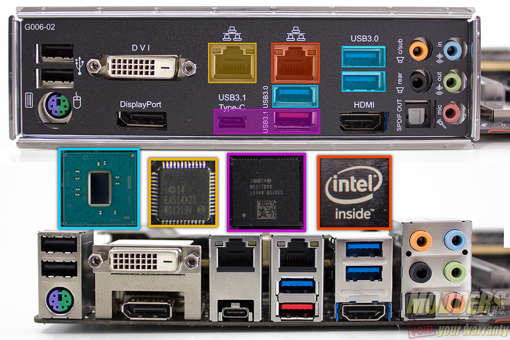
The rear PS2 port is provided by an ITE8628E Super IO chip which also handles system and temperature monitoring functions. There are two Gigabit Ethernet NICs included on the Gigabyte Z170X-UD5, one is Intel’s latest “Jacksonville” i219-V PHY while the other is an Intel i211AT. Fortunately, unlike the Z170-Gaming 7 motherboard, teaming is supported (skip to page seven for the quick verification test).
There is a DisplayPort 1.2 (Maximum resolution supported is 4096×2304@60Hz, a DVI-D port supporting up to 1920 x 1200 @ 60Hz and an HDMI port supporting 4096 x 2160 @ 24Hz. Unlike the Z170X-Gaming 7, the Z170X-UD5’s HDMI port only supports HDMI 1.2 as opposed to HDMI 2.0 since there is no Megachips MCDP2800BB like there was on the Z170-Gaming 7. For rear audio, there are five configurable analog audio jacks with one optical audio out.
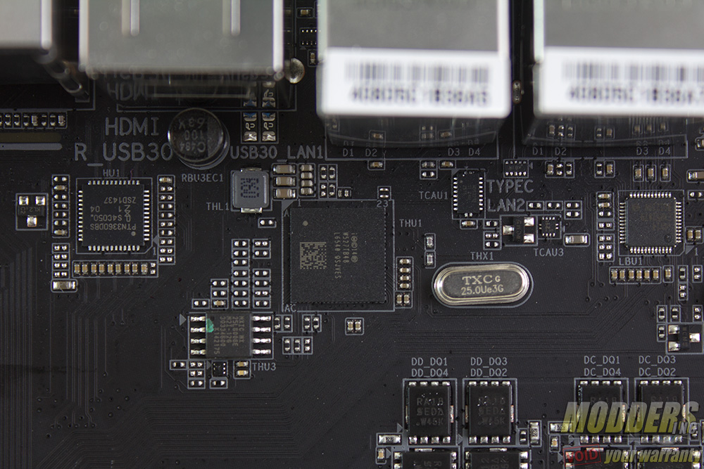
Three USB 3.0 ports are available via the Z170 chipset. Two USB 3.1 ports are provided, one is Type-A and one is Type-C via Intel Thunderbolt 3 DSL6540 controller with a Texas Instrument HD3SS312 switch. This is the future of connectivity and it is nice to see that the Gigabyte Z170X-UD5 is ready for it. It is pretty much essential at this point going forward even though there are not many devices yet that can fully saturate it yet.
