Gigabyte Z170X-Designare Review: A Playful Practicality
A Closer Look at the Gigabyte Z170X-Designare Motherboard
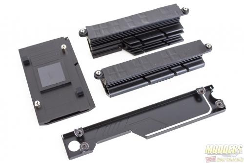
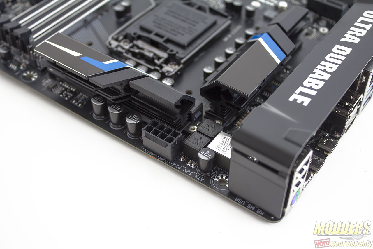
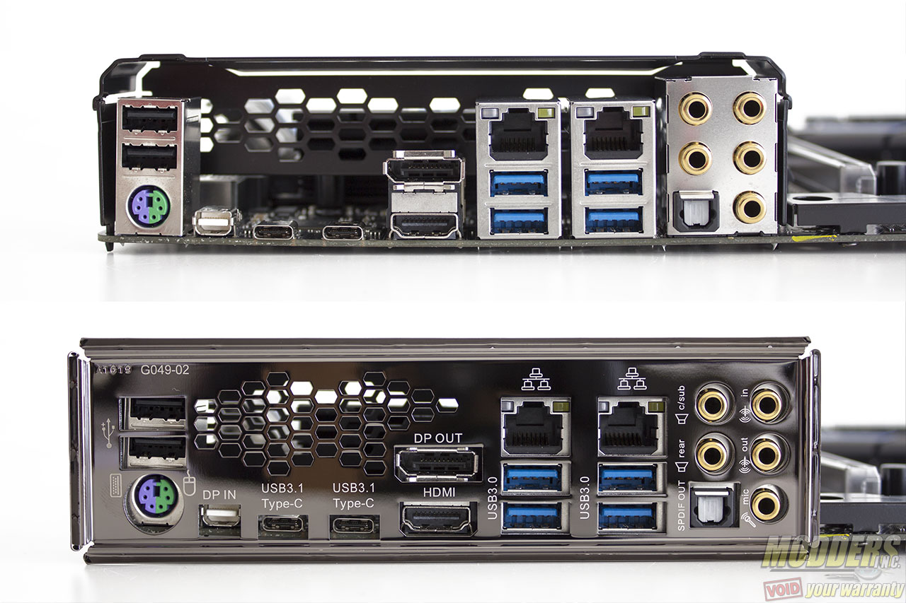
An IO cover is pre-installed similar to the Z170X-Gaming 7 and Z170X-Ultra Gaming. Although this is more of a cosmetic feature, Gigabyte has designed it so that warm air from the VRM can pass through and out of the IO shield (which has ventilation holes as well). This IO cover is made of metal and weighs 70 grams. It secures to the motherboard via two screws at the back but it also latches to the motherboard PCB for more stability.
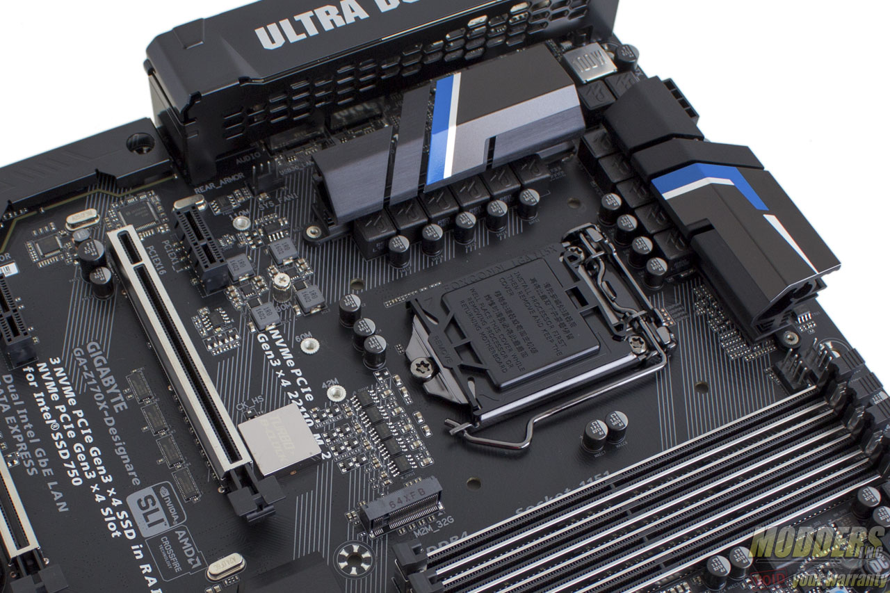
The VRM coolers are made up of two identical, non-heatpiped pieces weighing 50 grams each. These are black anodized aluminum heatsinks standing 26.65mm tall with the blue/grey accent thin metal sheet design glued on top so it is easily moddable should users find the blue color clashing with their color choice for a mod. Gigabyte uses a thick gray thermal tape in between the MOSFETs and the heatsink.
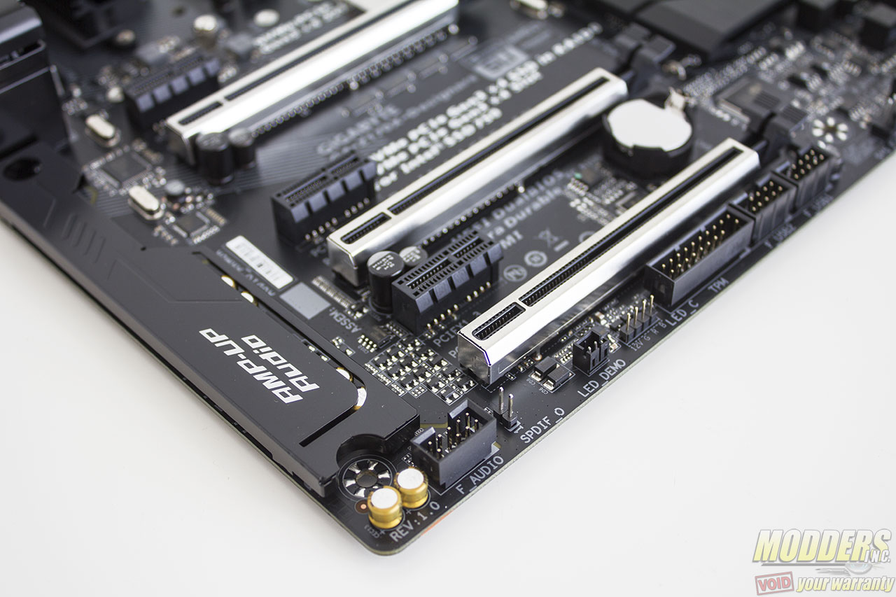
The chipset heatsink weighs 45 grams and the accent on it can be removed or modded in the same way as the VRM heatsink. A thin graphite thermal sheet is used as an intermediary between the chipset and this heatsink instead of a thicker thermal tape or thermal interface paste. The audio armor piece weighs 15 grams and does not act as a heatsink of any sort. It is purely cosmetic and easily moddable as well considering it mounts easily via screws from the rear.
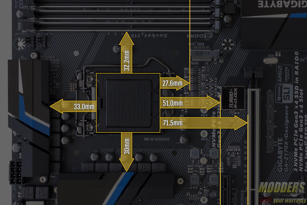
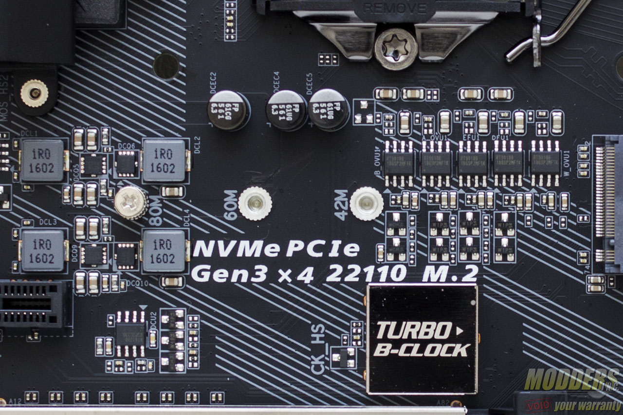
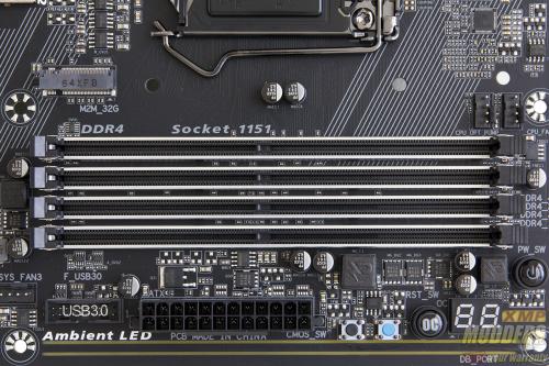
The space is very generous for the RAM clearance at 32.2mm compared to many motherboards that are 27mm or under. The layout is also quite similar to the Z170X-Ultra Gaming with the M.2 slot directly positioned right above the top-most PCI-E x1 slot and below the CPU socket where the bank of linear regulartors and MOSFETs for the minor CPU rails are. This M.2 slot supports up to 110mm long devices. Unlike the Z170X-Ultra Gaming motherboard however, the Z170X-Designare is equipped with the “Turbo B-clock” IC (it is hidden underneath a shiny metal housing), a secondary clock generator for refined BCLK overclocking.
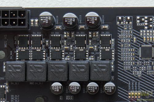
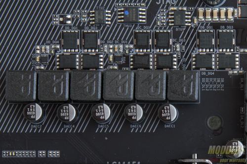
The main PWM controller is an Intersil ISL95856, a dual-output 4+3 phase capable IMVP8 controller from Intersil for the CPU+GT.There are three integrated drivers in total on this controller, two of which are on one output (voltage regulator A) while the third one is can be used on the voltage regulator that can be configured up to three phases. All of these drivers are used and additional Intersil ISL6625A drivers are utilized to drive Vishay SiRA18DP and SiRA12DP TrenchFET MOSFETs. Output filter has custom 500nH chokess with 561uF Japanese FP caps. This setup is almost identical to the Z170X-Ultra Gaming with the exception of having the phases doubled.
The 8-pin EPS12V CPU power connector is at the top right corner, tightly squeezed right above the VRM heatsink and beside two chokes. Gigabyte was wise to make the latch for this power connector facing upward so it is easier to release later during uninstallation. The 4-pin fan header for rear placed exhaust fans is positioned further down closer to the bottom edge of the rear IO.
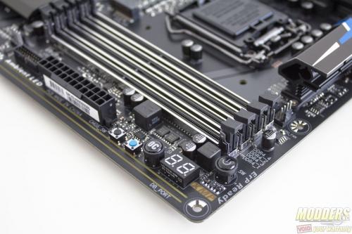
The DIMM slots have a metal “armor” around them and only lock on the top end part while the bottom part is fixed. A Richtek RT8120D is used for the memory VRM with three SiRA12DP FETs, a pair of 561uF FP caps and a 1KnH choke. Another 4-pin fan header is located here, right below the 24-pin connector.
A port-80 debug LEDwith onboard buttons for power, auto-overclock mode, reset and clear CMOS can also be found on the top right corner.
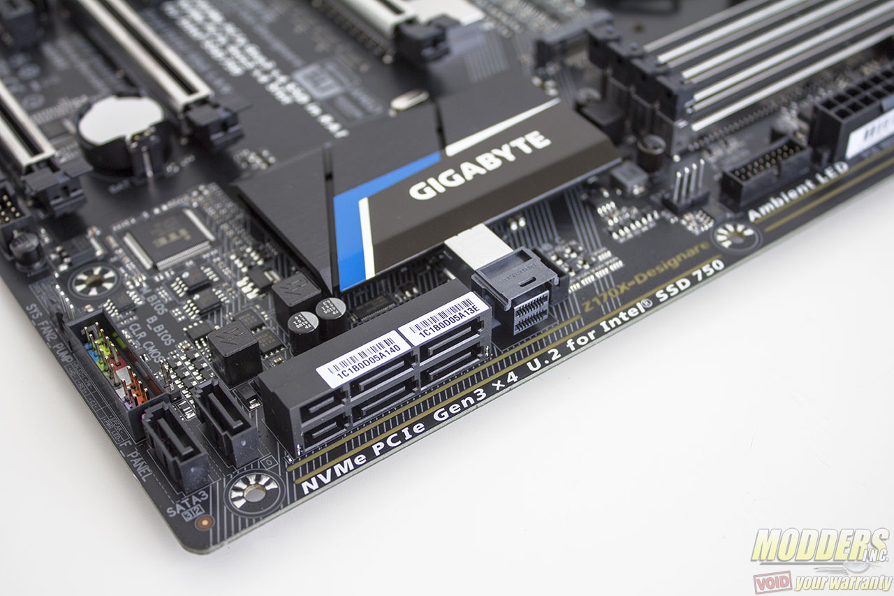
Onboard storage begins with a 19-pin USB 3.0 header right below the 24-pin power supply connector. This is natively from the chipset. There is also a thunderbolt connector header available for a Thunderbolt add-in card. Although these new crop of Gigabyte motherboards have the hardware onboard since their release, Gigabyte only officially announced on August 25, 2016. Thunderbolt 3 boasts up to 40Gbps compared to Thunderbolt 2’s 20Gbps. Gigabyte uses Intel’s Alpine Ridge controller unlike other motherboards which utilize a 3rd party solution for their USB 3.1.
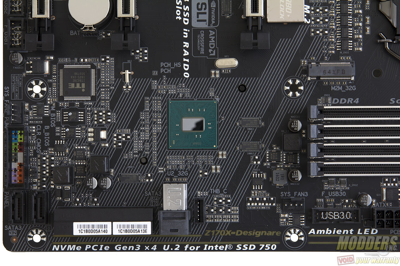
Provided are six SATA3 headers, two pairs of are angled which can be used as SATA Express, although do not hold your breath for any SATA Express devices any time soon. What is exciting however is the inclusion of an embedded U.2 connector.
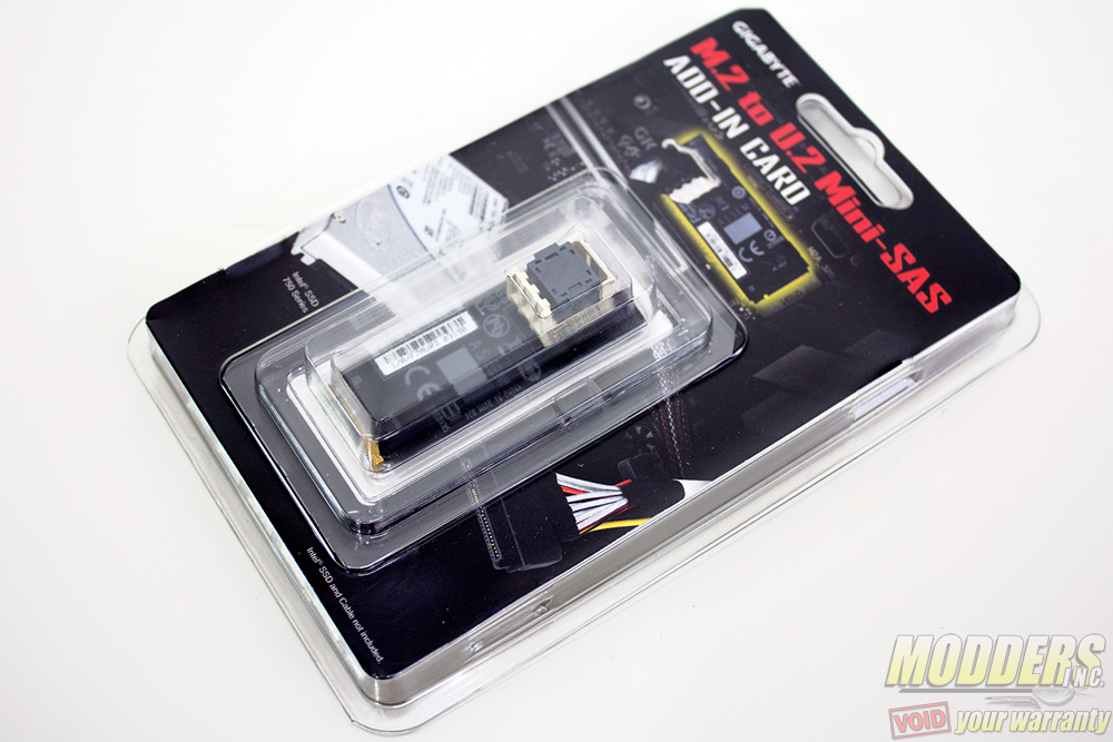
One m.2 slot is located right below the CPU socket which can also be used with an m.2 to U.2 Mini-SAS add-in card. It can be plugged into one of these m.2 slots and be able to run up to three NVMe SSDs in RAID 0 (M.2 or M.2 with U.2 converter + U.2 + PCI-E).
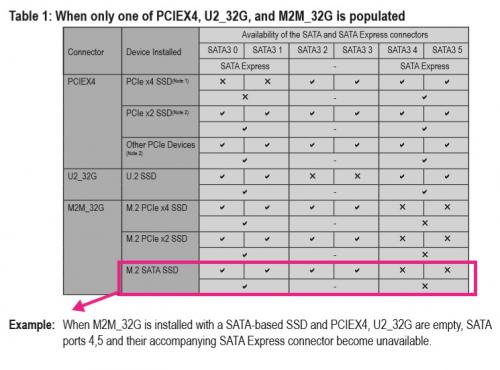
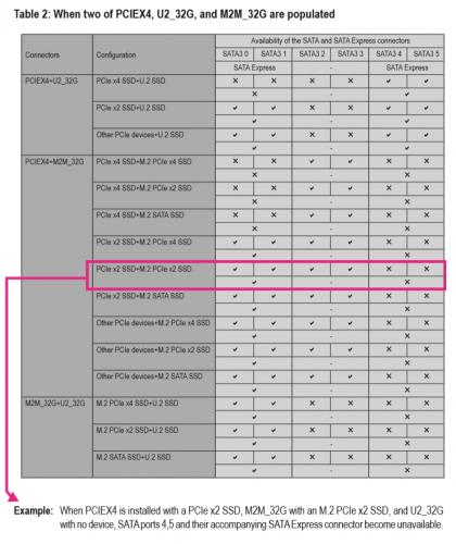
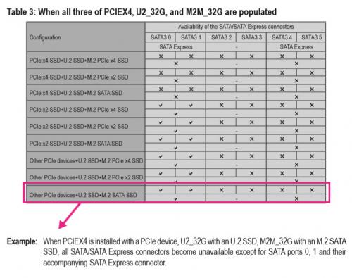
The Z170 chipset is very flexible when it comes to accommodating storage and it can actually support the three Gen 3 x4 SSD devices using switches. Gigabyte provides the following configuration for the internal storage:
If a drive is installed on the bottom-most PCI-E slot, SATA ports 0 and 1 are disabled, using ASMedia ASM1480 switches to toggle. Even if it isn’t an SSD installed here, as long as this slot is populated, SATA ports 0 and 1 are disabled. You can see that Gigabyte has prioritized the storage plexing so that it has as little interference to the rest of the lane allocation besides the SATA ports.
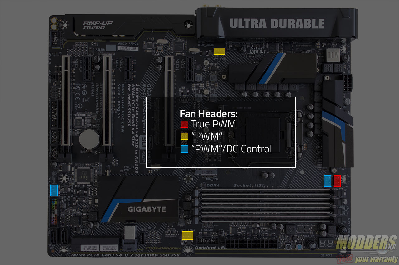
The last of the fan header is located right beside the front panel header on the bottom right corner. Despite all being 4-pin headers, they are not all the same. Only the CPU is a “true” PWM header with a GND, +12V, Sense and Speed control pin layout while the SYS_FAN1 and SYS_FAN3 have GND, Speed Control, Sense, VCC pin layout. There are no 3-pin DC control options available for the other headers except for the CPU_OPT_PUMP and SYS_FAN2_PUMP headers which have a GND, Speed Control, Sense, Speed Control pinout. Connecting fans in these headers allow for voltage control adjustment via UEFI.
Along the bottom right corner is the front panel header but this should be very easy to spot considering it is marked with the polarity and color coded. The G-connector accessory also makes installation easier. In addition to the clear CMOS button on the top right corner of the motherboard, there is also a jumper header option right above the front panel header bank.
For BIOS redundancy, Gigabyte includes a pair of Macronix 128-Mbit flash ICs. Unlike other motherboards which allows users to toggle between these ICs, Gigabyte’s backup will kick in automatically only when necessary.
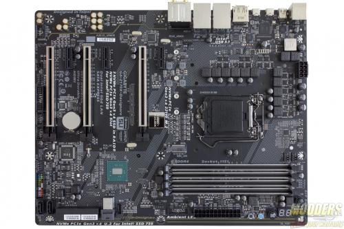
Expansion slot distribution is as follows (in order top to bottom):
- PCI-E 3.0 x1 via Z170
- PCI-E 3.0 x16 via CPU (x16, x8 when slot 4 is populated, switched by ASMedia ASM1480’s)
- PCI-E 3.0 x1 via Z170
- PCI-E 3.0 x16 via CPU (x8)
- PCI-E 3.0 x1 via Z170
- PCI-E 3.0 x16 via Z170 (x4, shares bandwidth with SATA 0, 1)
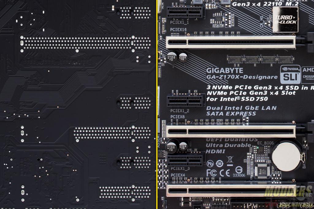
Like the rest of Gigabyte’s G1 gaming line, the Z170X-Designare motherboard’s PCI-E retention slots are reinforced with soldered-through shielding. This prevents the motherboard from getting damaged just in case something heavy drops on your video card that dislodges it.
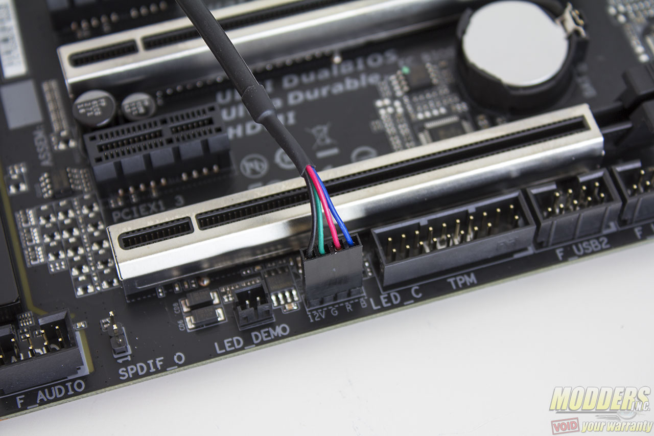
The rest of the headers along the bottom include a pair of 9-pin USB 2.0 headers, a trusted platform module header, RGB LED header and front panel audio headers with SPDIF output. The RGB LED header is for connecting RGB LED strips which then can be controlled in sync with the Gigabyte Z170X-Designare either via the Ambient LED under the UEFI or the desktop software application.
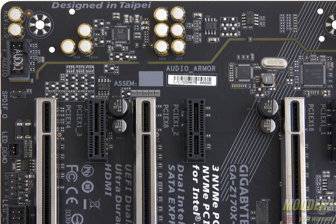
The audio subsystem is physically isolated from the rest of the PCB and audio is handled by a Realtek ALC1150 HD Audio codec. The ALC1150 has 115dB front DAC and 96DB DAC for the rest of the output channels and supports 24-bit playback/line in. This audio subsystem lights up with RGB LEDs (set to blue by default) lined up at the rear of the PCB that shine through the isolation border. Nippon Chemicon audio capacitors are used for filtering in this area and a Texas Instruments OPA1652 amp is used for the rear IO audio output which can drive up to 2k-ohm loads.
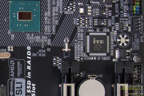
The rear PS2 port is provided by an ITE8628E Super IO chip which also handles system and temperature monitoring functions. A pair of USB 2.0 and four USB 3.0 ports are provided natively by the Z170 chipset.
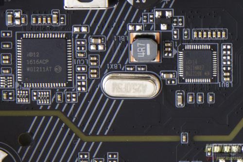
There are two Gigabit Ethernet NICs included on the Gigabyte Z170X-Designare, one is Intel’s latest “Jacksonville” i219-V PHY while the other is an Intel i211AT. Teaming is supported on some operating system versions.
There is a DisplayPort 1.2 (Maximum resolution supported is 4096×2304@60Hz and an HDMI 1.4 port supporting 4096 x 2160 @ 24Hz. Like the Gigabyte Z170X-Ultra Gaming, the Z170X-Designare is also equipped with a DisplayPort input connector.
For rear audio, there are five configurable analog audio jacks with one optical audio out with all the analog jacks having gold plating.
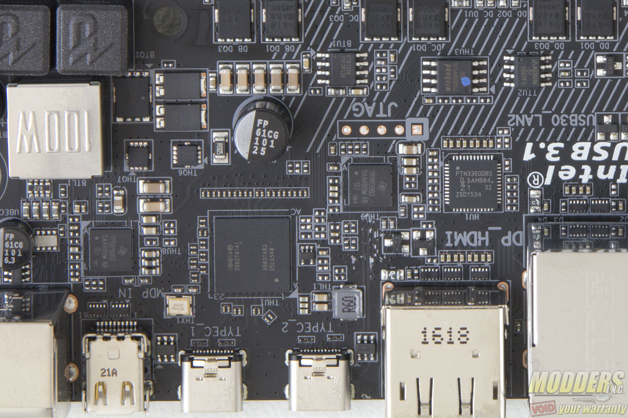
Two USB 3.1 ports are provided, both Type-C via Intel Thunderbolt 3 DSL6540 controller with a Texas Instrument TPS65982 switch. This setup implemented in the circuit can provide 20v x 5A on the USB 3.1 ports (Gigabyte hides some of these components under the 100W cover near the 8-pin EPS header).
