Gigabyte X99 Phoenix SLI Motherboard Review
A Closer Look At The Gigabyte X99 Phoenix SLI Motherboard
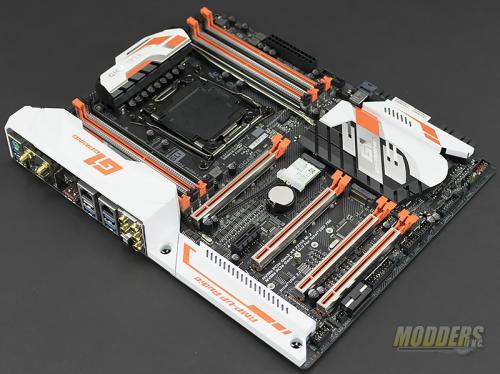
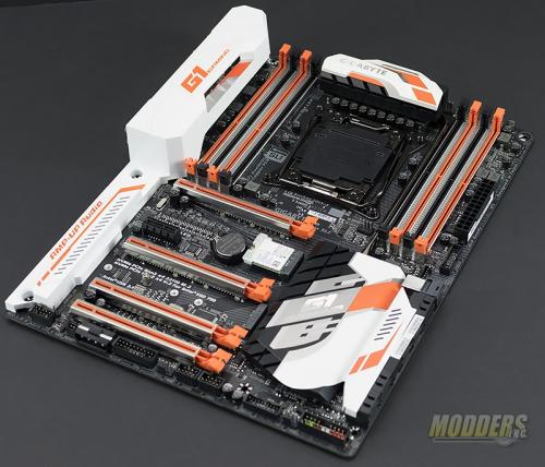
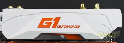
At first glance, you’ll notice the striking color scheme. Gigabyte chose to go with a black PCB with white, orange, and silver colors on the PCH heatsink, VRM heatsink, and the I/O cover. Personally, this is a welcome change from black and red, or black on black colors of other motherboards. Don’t get me wrong, I still like them but a little change now and again is welcome. Plus, I think the colors will blend in very will with a Sci-Fi mod such as a Mechwarrior, Titanfall, or a spaceship mod.
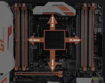
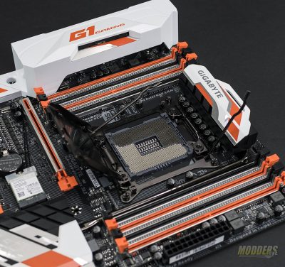
The area around the CPU is fairly uncluttered and most heatsinks designed for LGA2011-V3 should fit without an issue however, larger heatsinks may block the first two memory module slots on each side of the CPU socket. The memory modules measure about 25.6mm from the CPU socket. The VRM heatsink is a little further away at 30.2mm and the first PCIe x16 slot is 45.4mm from the CPU socket.
If you’ve never built an Intel Enthusiast (X99)platform before, they are a little different. The CPU retention mechanism has two locking arms as compared to one for the Consumer level (Z170). In order to get the CPU lid up, you must unlock one of the arms before the other will release. The CPU socket has a few extra pins that are used to increase stability and enhance overclocking of the CPU, memory and cache.
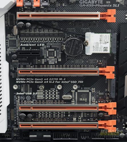
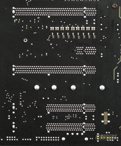
Gigabyte has redesigned the PCIe slots to give a little better room when running a 2 or 3-way SLI set up. Electrically, you can see by the back side of the motherboard the first two PCIe slots are x16 whereas the last two slots are a max of x8. The first PCIe x16 slot and the first PCIe x8 slot share bandwidth. The same goes with the second PCIe x16 slot and the 2nd PCIe x8 slots. When all four slots are populated each slot runs at a maximum of x8. There is a PCIe x1 between the top two PCIe slots. There is s single PCIe Gen 3 x4 M.2 slot on the X99 Phoenix SLI. It is NVMe capable and supports M.2 drives up to 110mm in length. Gigabyte’s PCIe armor is present around the PCIe slots as well. This is designed to help reinforce the PCIe slot to keep it from getting damaged from heavy graphics cards.
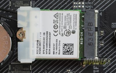
An Intel dual band wireless network adapter is present between the first and second PCIe slots. This wireless card supports 802.11ac dual band with 2×2 plus Bluetooth 4.2 and the specifications state the speed of this card is up to 867 Mbps.
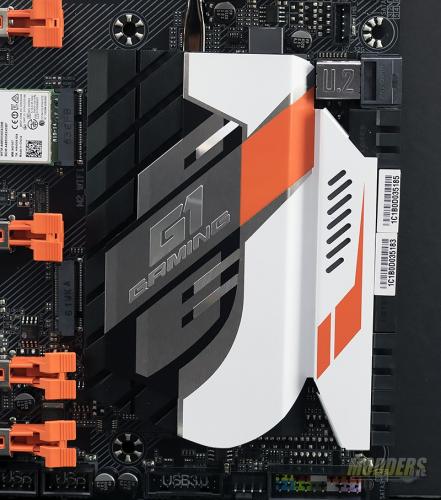
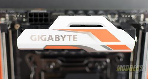
The PCH is covered by a passive heatsink that is decorated in the white/orange/silver color scheme and the same color scheme is present on the VRM heatsink. The 8-pin power connector is located just up and to the left of the VRM heatsink. The connector is positioned so the retention clip is to the top of the motherboard allowing easier removal.
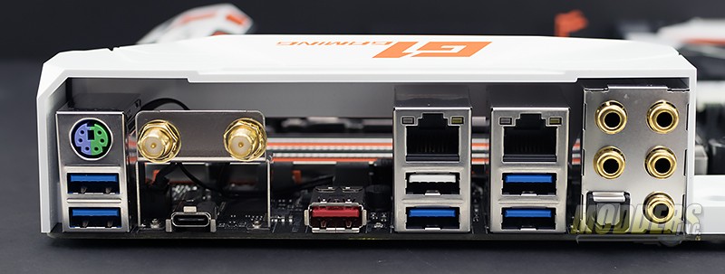
For rear I/O, Gigabyte has included, a PS/2 combo port, 2 SMA antenna connectors, USB 3.1 type C, USB 3.1 type A (Red connector),6 USB 3.0 ports (Blue and White), dual RJ46 LAN ports, 5 3.5mm audio jacks, and one optical S/PDIF connector.
Edge connectors on the board include, front panel audio, 4-pin molex connector used to deliver extra power to the PCIe slots when using SLI, two USB headers, front panel USB 3.0, and the front panel connectors. Gigabyte has included their G connector which makes it easier to connect the case power, reset, and LEDs.
A total of 10 SATA ports are available on the X99 Phoenix SLI. A U.2 port is provided as well. U.2 provides x4 lance of PCIe to a traditional 2.5″ SSD format. Currently, only the Intel 750 series SSD can utilize the U.2 connector. SATA express is still provided although, I have yet to see a device that utilizes SATA express.
The I/O cover and the audio circuit cover are both made from plastic and are held to the motherboard with just a few screws. The underside of the I/O cover has a small strip of RGB LEDs that connect to a 4-pin header behind the antenna connectors. The audio cover is back lit from the audio path LEDs.
