Gigabyte X99 Gaming 5P Motherboard Review
A closer look at the Gigabyte X99 Gaming 5P Motherboard
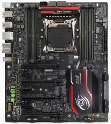
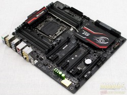
The Gigabyte X99 Gaming 5P is an E-ATX form factor motherboard. The E-ATX standard is just a touch wider than ATX at 12.5″ (E-ATX) vs 9.5″ (ATX). This is an important aspect to look at when purchasing a motherboard, as the E-ATX may not fit into your case.
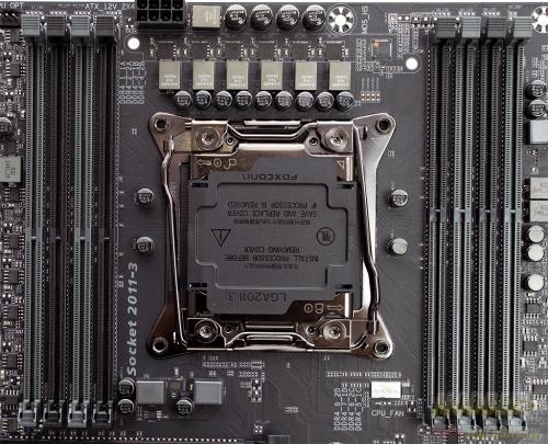
The area around the CPU is uncluttered. There is a bit of space between the CPU socket and the memory modules. For those of you that use air cooling on the X99 platform and depending on your cooler and memory configuration, memory to cpu cooler interference may still occur. The Gaming 5P has eight memory slots available and can support up to 128 Gb of DDR4-3333 RAM.
A single 8-pin power CPU power connector is located at the top edge of the motherboard just behind the VRM heatsink.
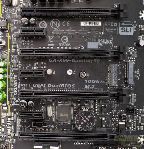
The Gaming 5P contains 4 full length PCIe slots and 3 PCIe x1 slots. Mechanically the full length slots will fit a GPU in them. As you can see, slots 1 and 3 are electrically pinned out to x16 whereas slots 2 and 4 are x8. Typically when all four slots are filled on the motherboard with GPUs, they all run at x8. However, with the Gaming 5P, the breakdown from slot 1 to slot 4 would be : x8, x8, x16, x8. In a 3-way (Slots 1, 3, and 4 populated) scenario the breakdown is x16, x16, x8. This layout uses all 40 PCIe lanes available to the GPUs.
A total of ten SATA 3 connections are available on the Gigabyte X99 Gaming 5P; all of which are controlled via the Intel PCH. A single SATA express connection is available. When either a SATA express drive or an M.2 drive are used, the total number of SATA connectors drops from ten to eight. The motherboard supports RAID 0, RAID 1, RAID 10 and RAID 5
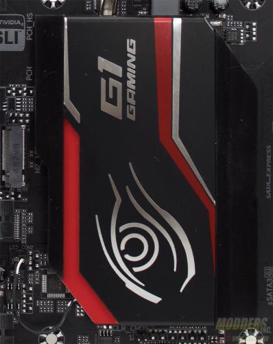
The PCH is passively cooled by a large heatsink that is connected via heatpipe to the heatsink that sits ontop of the VRM modules above the CPU socket.
You will notice a small wire that leads from the heatsink to the motherboard. This wire provides power to the LED light at the edge of the heatsink and can be controlled via the Amient LED application in the Gigabyte App center.
The bottom edge of the motherboard features the front panel connectors. At the far left is the front panel audio connector. Moving towards the right, there is a Molex power connector that provides extra power to the PCIe slots when using a multi-GPU configuration. Next are two USB 2.0 front panel connectors that provide two USB 2.0 ports each. The power, reset and LED connectors are at the right edge of the board. The Gaming 5P has a total of five fan headers, including the CPU_OPT connection. Front panel USB 3.0 is provided by a USB 3.0 header located near the ATX power connector.
he back panel I/O features two PS/2 ports, six USB 2.0 ports four of which are designated as DAC-UP, and are yellow in color. According to Gigabyte the DAC-UP USB ports pull power from their own dedicated power source on the motherboard which delivers cleaner power to the ports and reduces fluctuations. Four USB 3.0 ports are on the back panel as well as the wired networking RJ-45 port and gold plated audio port with a digital-optical port. The last two holes in the I/O shield are meant to be used with a mPCI wireless card and the holes are for the antennae. Take note of the white USB 3.0 port at the bottom of the Rear I/O. This is what Gigabyte calls their Q-Flash port. This allows users to update the BIOS via a flash drive without having a CPU and memory installed. Simply download the BIOS file to your flash drive, make sure the motherboard is powered down, plug in the flash drive and power the system on. Wait until the flash is done and you’re good to go.
The Rear I/O shied is LED lit similarly to the PCH heatsink. There is a small wire that runs from the I/O shield to the motherboard. This LED is also controlled via the Ambient LED application within the Gigabyte App center.
