Gigabyte GA-Z87X-UD4H Motherboard
Gigabyte GA-Z87X-UD4H Overview
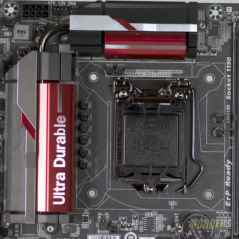 |
The area around the CPU socket is standard per Intel’s specifications. The pins in the CPU socket are gold plated to allow better electrical conductivity as well longevity. The VRMs and ICs surrounding the CPU socket are passively cooled using heatsinks.
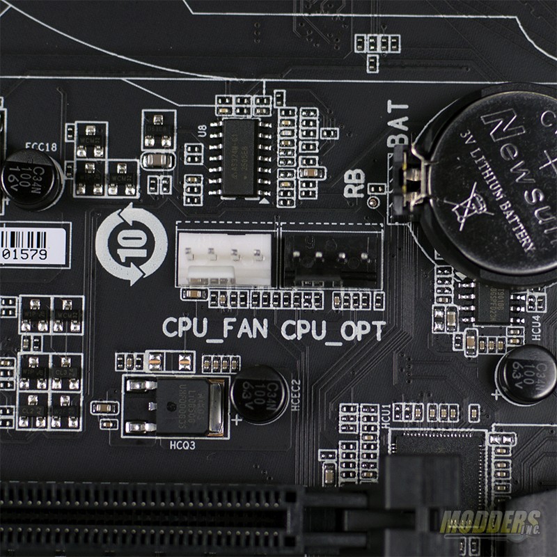 |
One of the nice features about the Gigabyte GA-Z87X-UD4H is the dual fan headers just below the CPU socket. This is extremely useful for those who use water cooling or for those users that have air coolers with two fans. Each header is independently controlled and monitored in the BIOS.
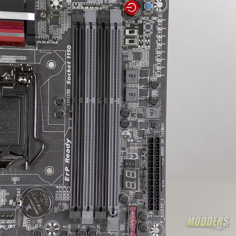 |
There are a total of four memory slots on the Gigabyte GA-Z87X-UD4H and supports Dual Channel DDR3 configuration. To use Dual Channel both memory slots of the same color need to be populated. The Gigabyte GA-Z87X-UD4H supports memory speeds up to DDR3 3000.
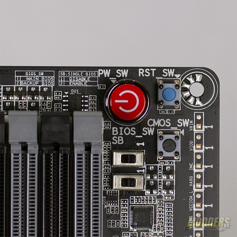 |
Gigabyte has opted to put controls directly on the motherboard. While this feature is not necessarily new it is a very handy to have. First up, the big red button is the power switch. The blue button right beside it is the reset switch. Just below the reset button is the clear CMOS button. In case of a bad overclock or other configuration error, unplug and power down the system and a simple press of the button will set the BIOS back to factory defaults. Below the power and reset switches are the control switches for the Dual BIOS functionality of the GA-Z87X-UD4H. There are two DIP switches that either turn off or on the Dual BIOS feature and tell the motherboard which BIOS, primary or secondary from with to boot. Along the edge of the motherboard to the right, there are voltage measurement points that can be used to measure voltage with a multimeter. Pin 1 of each test point is power and pin 2 of each is the ground.
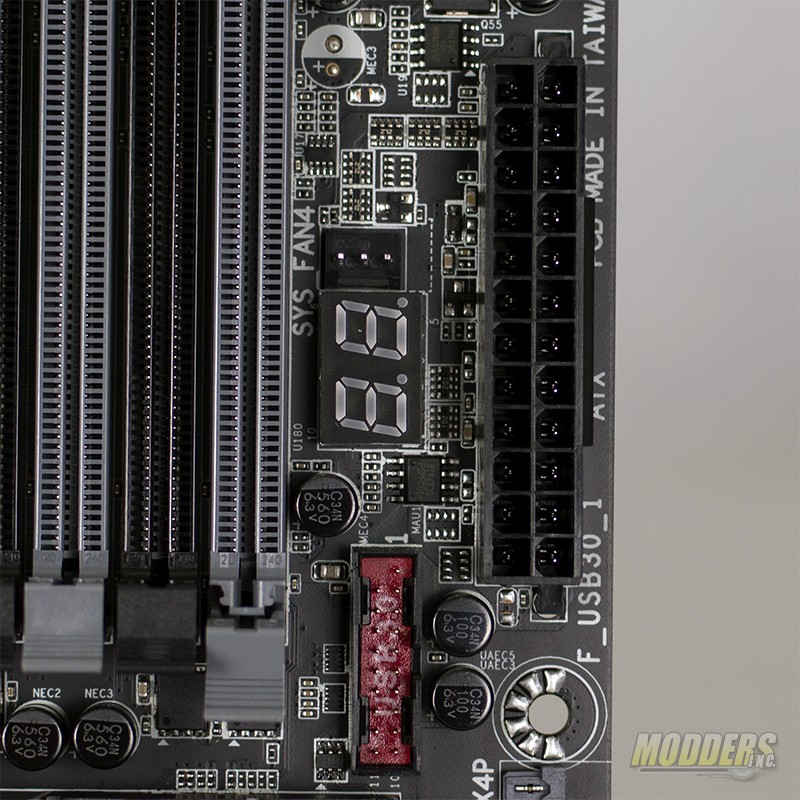 |
Moving along towards the bottom of the board, we hit the ATX 24-pin power connector. To the left of the power connector is the LED diagnostic display. The LED display can be used to troubleshoot reasons why the motherboard will not post correctly using the codes in the back of the user manual. Just below the LED diagnostic display is the first of two USB 3.0 headers for front panel connections. Most modern cases include the USB 3.0 cable.
