EVGA Z170 FTW Motherboard Review: An Overclocking Gambit
A Closer Look at the EVGA Z170 FTW Motherboard
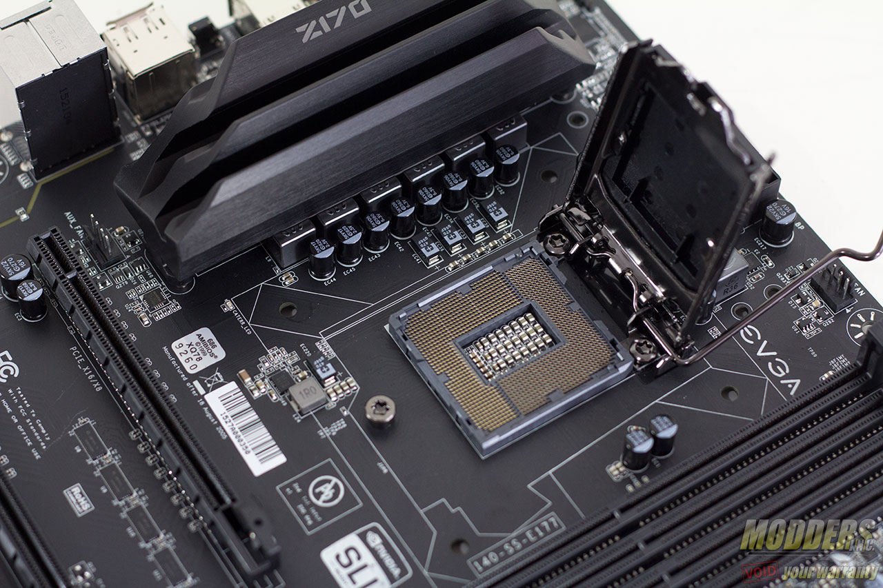
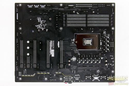
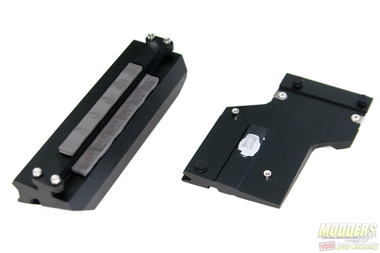
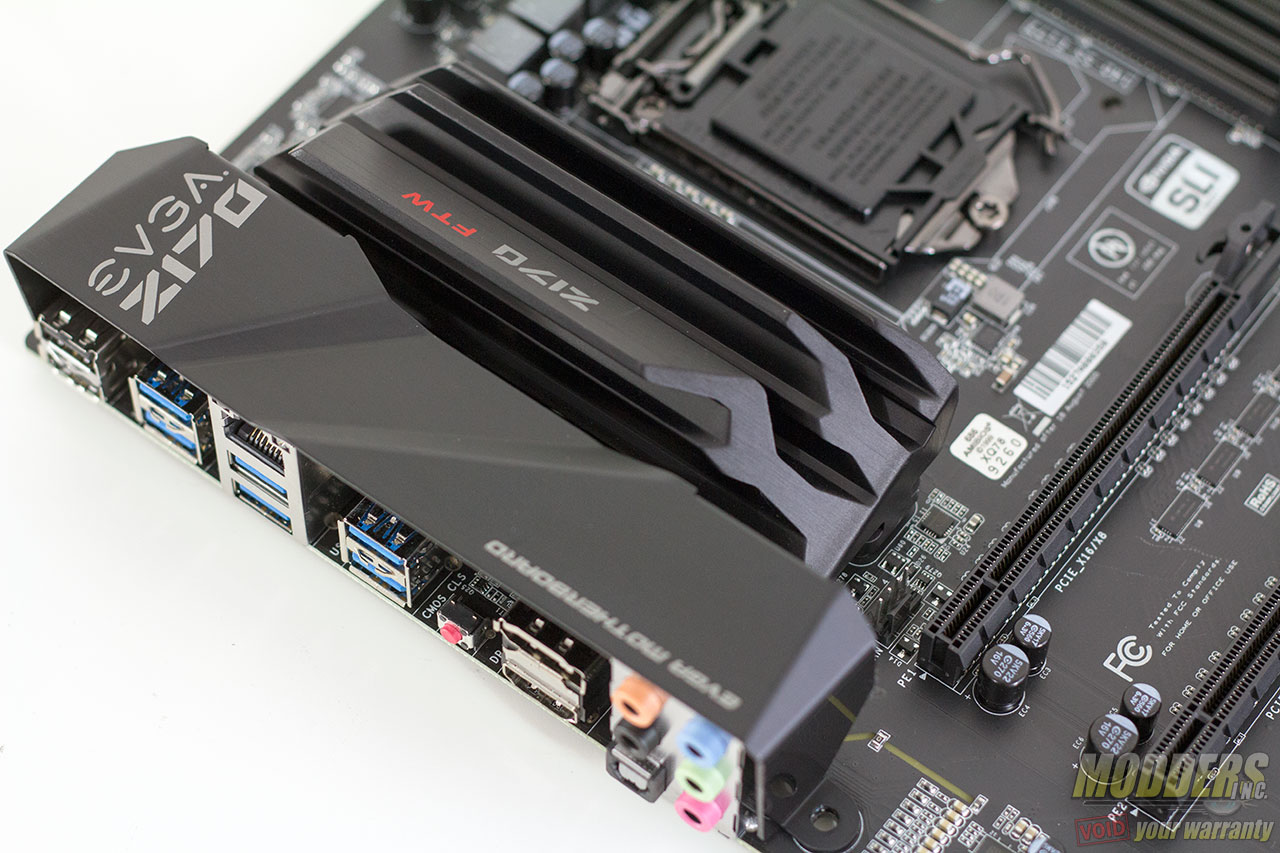
With the FIVR out of the picture, VRMs and their heatsinks are going to be in focus once again. EVGA’s VRM heatsink on the FTW is substantial, not in the usual way with large heatpipes extending to the chipset but just purely in size and weight. Weighing 228 grams all by itself, the VRM heatsink is a large solid aluminum block anodized black that requires four screws to hold in place properly. Thick thermal pads interface between the CPU and System Agent voltage regulator components.
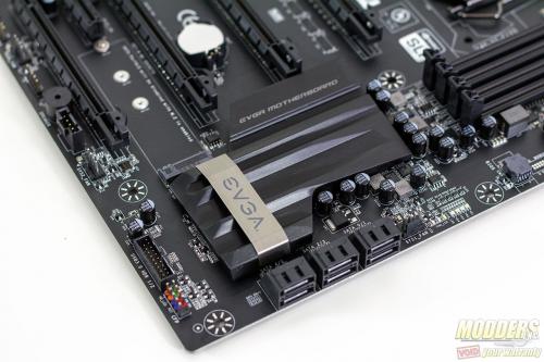
The chipset heatsink is also a solid aluminum piece clocking in at 84 grams but uses thermal paste to interface with the Z170 chipset. This cooling is actually overkill for the 6W TDP chipset (even though it runs hotter than the Z97’s 4.1W) but it looks great nonetheless, especially with the brushed metal band accent which are held in place by a screws on both ends at the back so users can easily remove and replace it for a modding project.
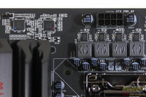
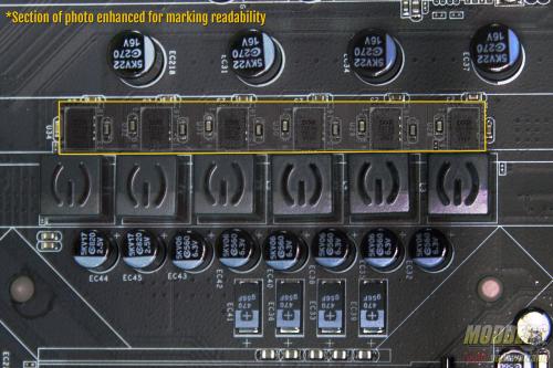
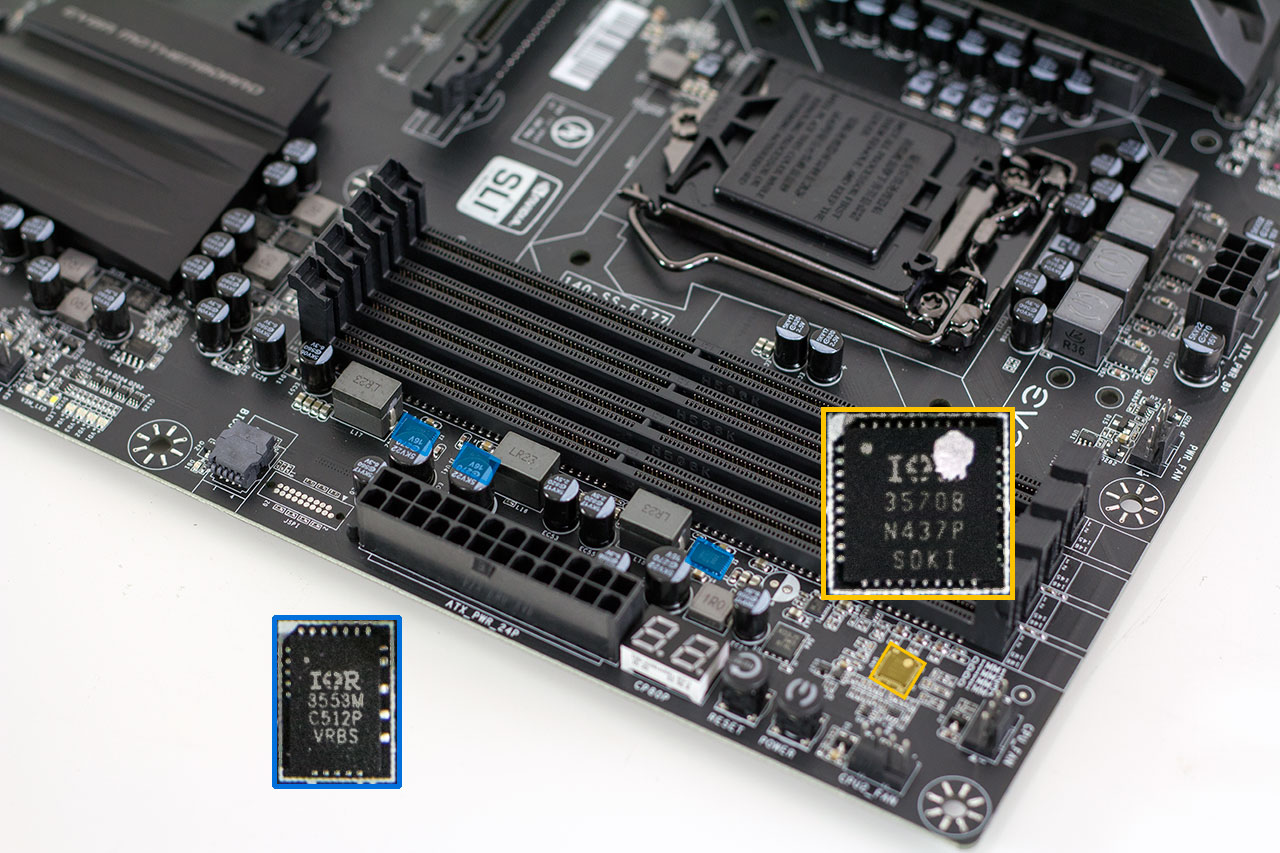
EVGA’s main focus has always been and will most likely always be enthusiasts who love overclocking so their VRM design choice takes that approach with dual IR35201’s, International Rectifier’s new digital IMVP8 dual output PWM controller. One is configured with 5-phases for the CPU and one phase for the System Agent while the other is configured only for the 4-phase integrated graphics, all using 40A IR3553 PowIRstage packages which helps with the efficiency and PCB space. You can tell which IR3553Ms are for the CPU because the ones for the IGP power do not have a heatsink on them, although there are three mounting holes available should users want to add one (two on the right side closer to the DIMM slot and one close to the CPU VRM).
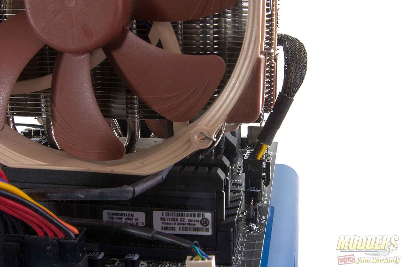
The PWM controllers are positioned to the left side above the VRM heatsink however, the 8-pin CPU power connector is placed right in the middle top, which makes it challenging to plug in the 8-pin CPU power cable when using a large heatsink such as the Noctua NH-D15S used in this photo, even on a test bed.
With the exception of some capacitors on the audio area and some POSCAP capacitors for output filtering, EVGA uses all solid Taiwanese AP-Con 5K capacitors and their usual high-current customized inductors (with their logo embossed on the top). Six 560uF solid capacitors and four 470uF tantalum capacitors with five 360nH chokes are in the CPU output. The System IO voltage is handled by a single phase IR3898 voltage regulator (single package controller + MOSFET) below the CPU socket with a laptop style 1k nH inductor and 470uF tantalum capacitor.
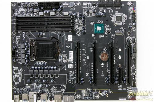
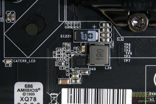
Skylake brings DDR4 support to mainstream desktop space in dual-channel form. EVGA uses single side latching DIMM (top only) to make it easier to install/remove DDR4 modules even with a long graphics card installed. Memory power is handled by an IR3570 configured for 3-phases with more IR3553 PowIRstages similar to the CPU VRM. Up to 64GB of DDR4 support is available with speeds of 4100+MHz supported in the latest UEFI version 1.03 update. Also on the corner edge above the 24-pin CPU power connector are the onboard power and reset buttons as well as a Port-80 debug LED which also functions as a CPU temperature display once the system has fully booted to the operating system.
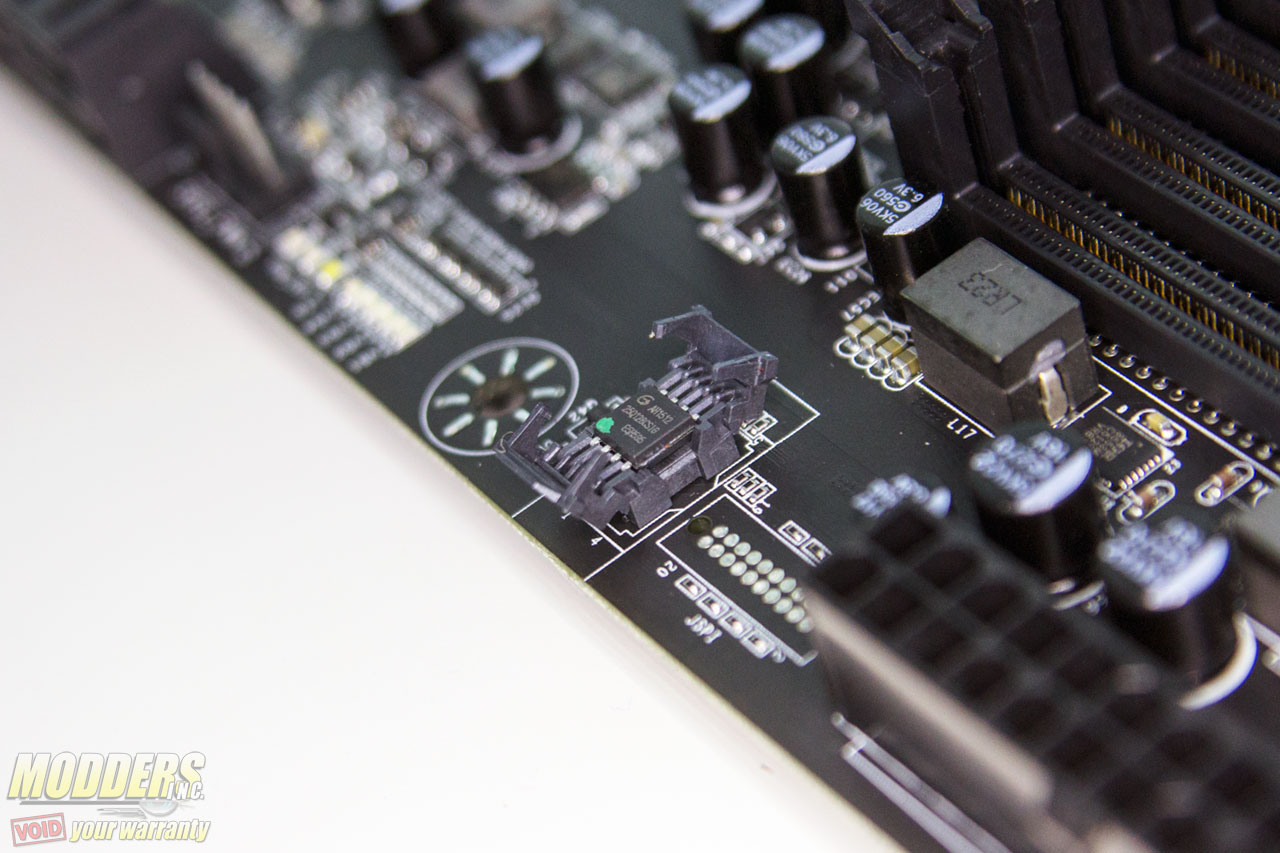
Right below the 24-pin CPU connector is the a socketed Gigadevice 25Q128CSIG flash. Although there are no BIOS redundancy options other than reset, a socketed chip option allows users to manually replace it if needed compared to a soldered part.
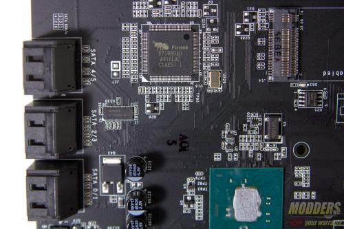
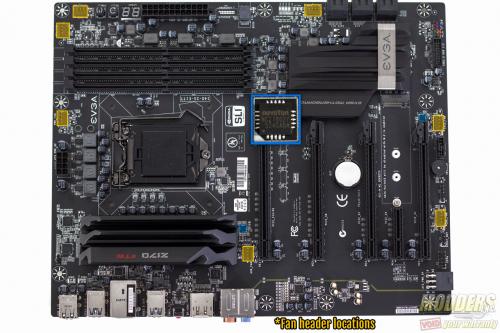
A Fintek F71889AD SuperIO chip located underneath the chipset heatsink covers a lot of the functions on the board including hardware monitoring, PS/2, Port-80 debug, and provides up to three PWM fan headers with S.M.A.R.T. fan function (CPU1, CPU2 and CHA fan headers). These three fan headers can also be adjusted in DC mode with 1% fan speed granularity and in PWM mode, can be set to adjust with system or CPU temperature as needed. With the aid of a pair of Nuvoton NCT7802Y (each on their own can control up to three), there are four more fan headers for a total of seven: SYS1, SYS2, PWR and AUX headers by default are in DC mode (with 5% fan speed granularity) but can toggle to PWM function as well.
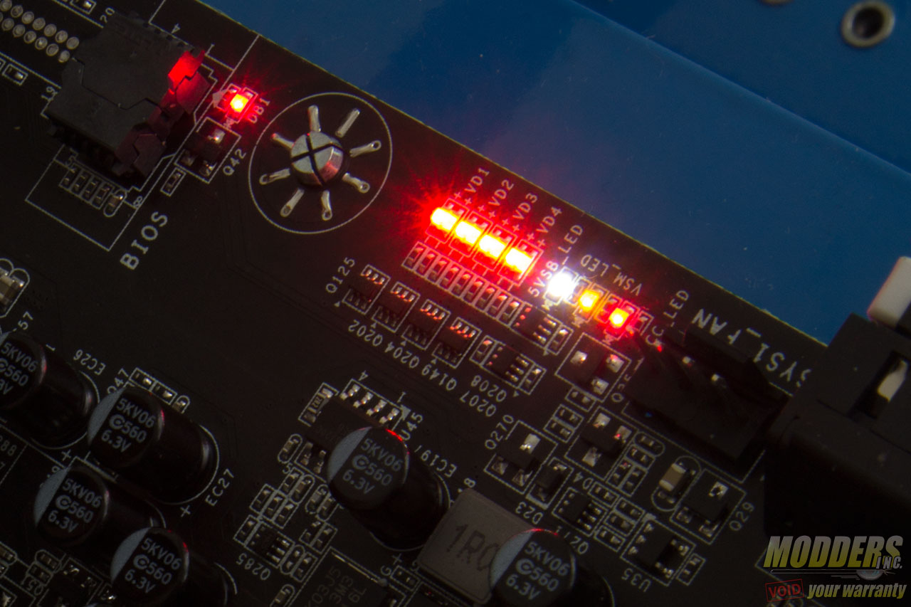
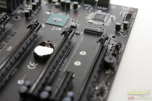
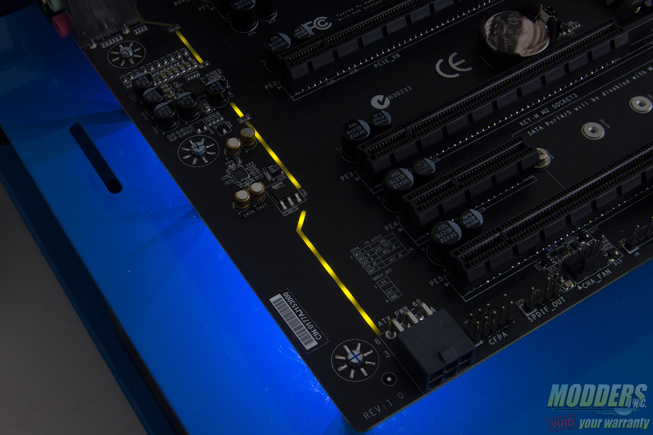
In addition to the Port-80 debug LED, a bank of voltage debug LEDs are on the right side edge as well between the BIOS chip and the SYS1 fan header as well. In terms of storage, there are six SATA 6G ports, all from the Z170 chipset with no extra options from 3rd party controllers. A single M.2 slot is available and shares bandwidth with SATA ports 4 and 5 switched by a Texas Instrument HD3SS3415 Gen 3.0 4-channel switch. Along the bottom right side corner edge also sits a 19-pin USB 3.0 fan header via the Z170 chipset and a color-coded front panel header.
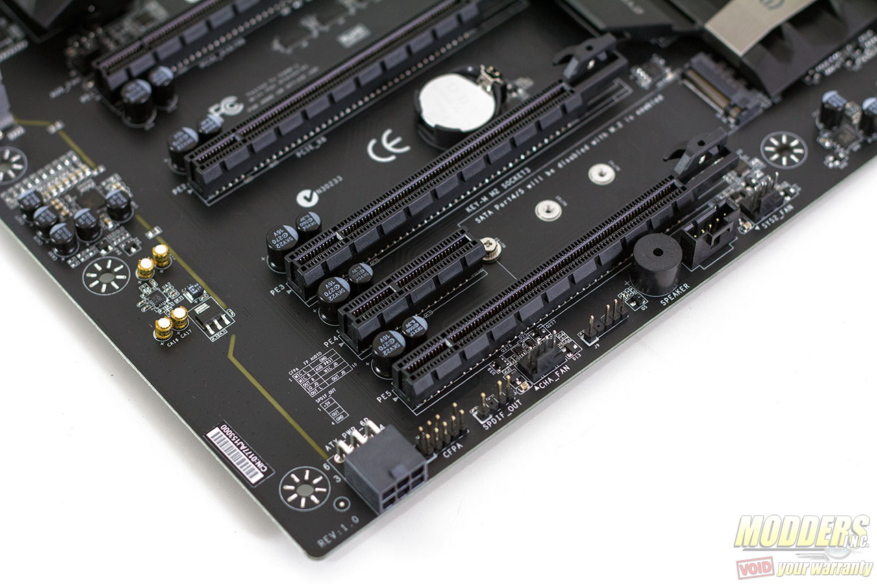
Continuing on the bottom row is a Thunderbolt GPIO header, embedded post-code speaker, EVGA EV gauge accessory header, SPDIF out header and front panel audio header. The pinouts for these audio headers are printed on the PCB right beside the bottom PCI-E expansion slot. Lastly, there is a 90-degree angled 6-pin power connector for additional PCI-E power.
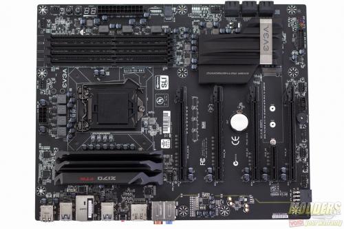
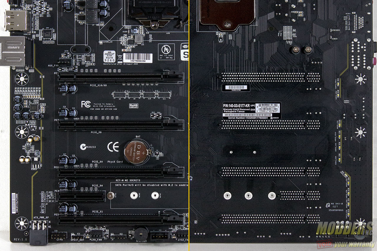
PCI-E Lane Distribution is as follows from top to bottom (physical: electrical):
- PCI-E 3.0 x16 via CPU: x16 with single card or x8 if second PCI-E 3.0 x16 via CPU is populated.
- PCI-E 3.0 x16 via CPU: x8
- PCI-E 3.0 x16 via PCH: x4
- PCI-E 3.0 x4 via PCH: x4
- PCI-E 3.0 x16 via PCH: x1
The PCI-E x16 locking mechanism is a top-release latch so instead of pressing down when facing the motherboard directly, users have to press at the top side of the expansion slot to release the PCI-E. I keep an old DDR module handy for releasing this latch when I want to uninstall a video card and have a large CPU heatsink installed. The unfortunate design choice about this layout is how close the top two PCI-E 3.0 x16 wired to the CPU is to each other. There is only space for dual-slot video cards and it sits quite close for comfortable airflow and practical SLI usage.
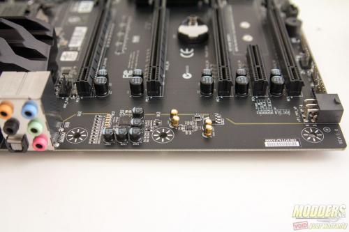
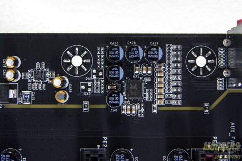
PCB separated audio is a popular trend for onboard sound and EVGA follows suit on the Z170 FTW, this one even has 11 white LEDs on the rear that cuts through and illuminates the separated area from front view as well. The Z170 FTW uses Realtek’s ALC1150 HD audio codec and can be configured for up to 8-channel audio. For those using headphones that need to be driven, EVGA uses a Maxim-Integrated’s MAX97220B direct drive headphone amplifier and with Nichicon MW series audio capacitors (users will need to plug in their headphones on the rear IO).
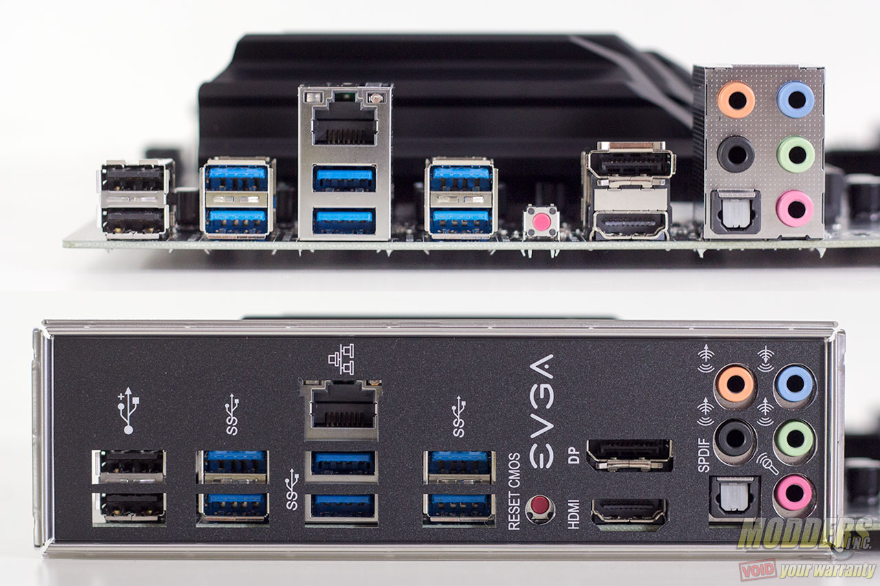
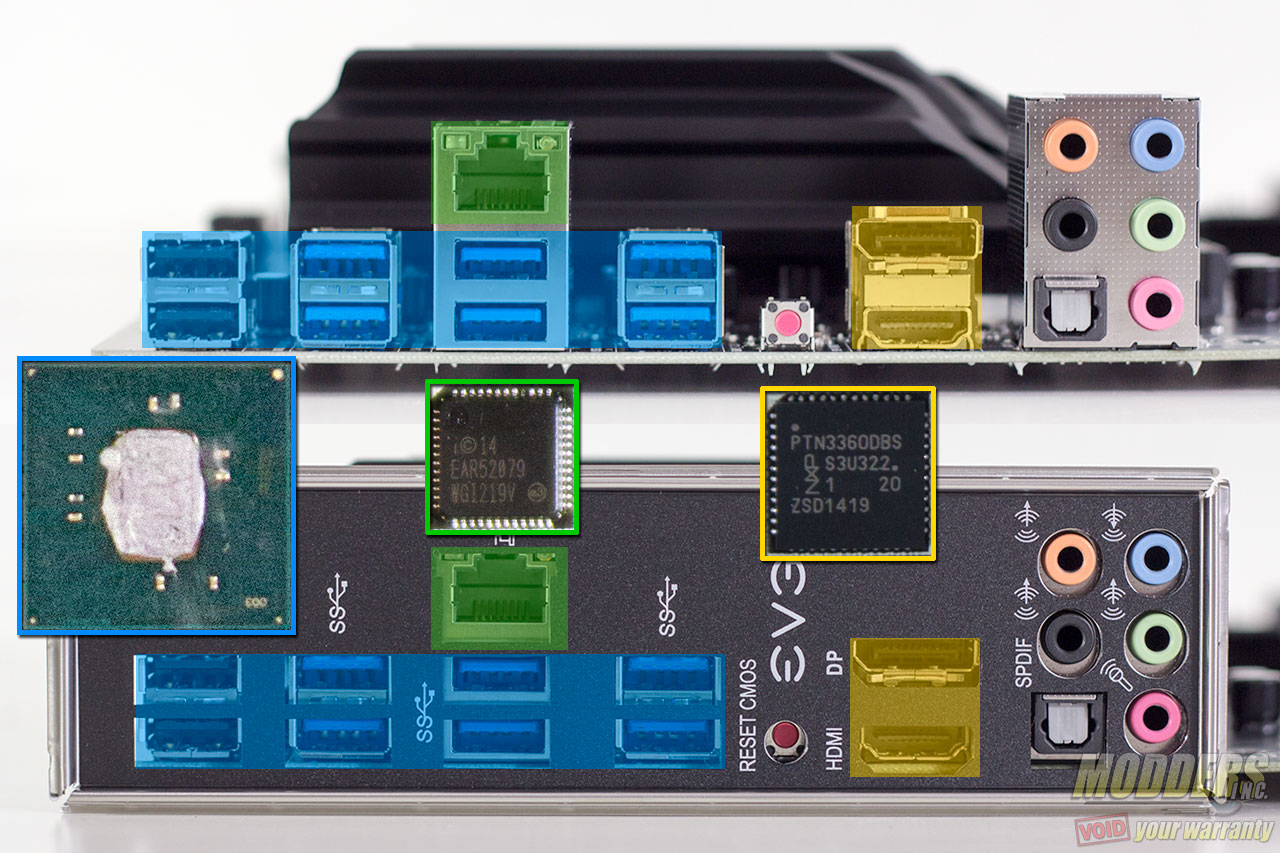
At the rear, there are five analog audio jacks with one optical audio port. HDMI 1.4 and DisplayPort 1.2 for use with Intel’s integrated graphics provides up to 4K display support. All two USB 2.0 and three USB 3.0 ports in the rear are via the Z170 chipset with no 3rd party controllers. Intel’s latest “Jacksonville” i219-V is used for the Gigabit Ethernet, improving efficiency further from previous generation “Clarkville” controllers. For performance tweakers, the CMOS reset button is just one push away via a small red button between the USB 3.0 ports and the display outputs.
Aside from a labeled IO shield, an IO cover accessory is also included, first seen in the EVGA Stinger motherboard.
