Enermax ETS-T40Fit CPU Cooler Review: A Twist on a Classic
Installation of the Enermax ETS-T40fit
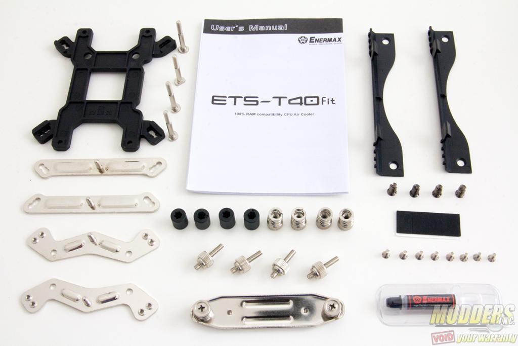
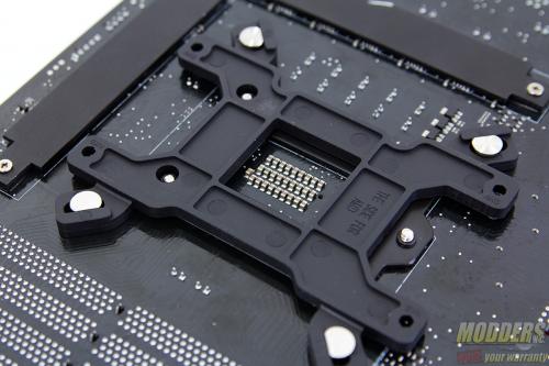
Both Intel and AMD users will use the provided ETS-T40fit backplate. As always before starting, make sure that all the parts listed in the user’s manual are included in the package and lay them all out for easier installation.
For Intel systems, the backplate has three different positioned holes to accommodate LGA775, LGA1366 and LGA115x sockets. Because people have been asking, yes LGA115x covers every single socket including LGA1151, LGA1150 and LGA1156 because the mounting hole distance is exactly the same for all of those models.
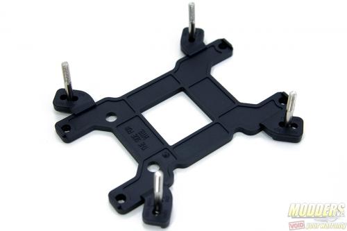
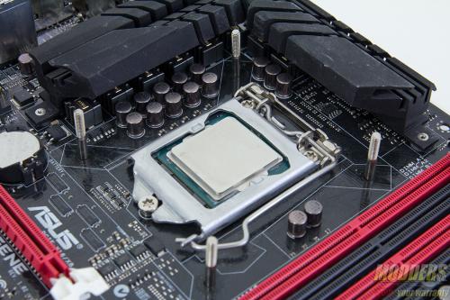
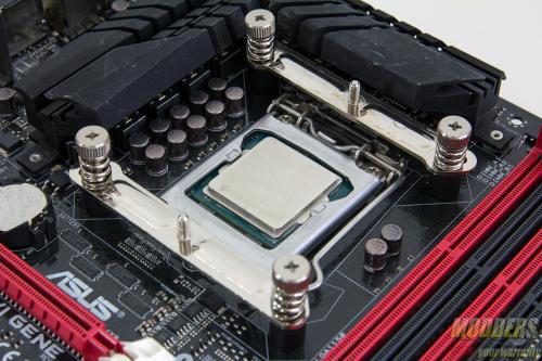
The first step is to pass through the position screw posts through the backplate. Since the test bed on this review uses an Intel LGA115x socket, the photos below shows that procedure although other than the mounting hole position, the steps are identical. The position screws can only be passed through the backplate in one way because of the stop-gap holders on the edges. The grip is also fairly tight so these position screws do not just come off if the backplate assembly is lifted.
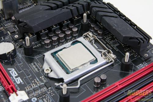
Position the backplate appropriately and take note of the position of the two holes at the top of the socket at the back of the motherboard. After positioning, plastic standoffs are secured on the position screws that further hold the backplate assembly in place. Like the backplate and position screws, the grip is fairly tight once fully passed through so installation is easier even on a vertical surface such as a motherboard installed inside a case.
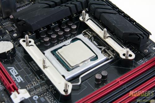
After the plastic standoffs, decide how the heatsink will be mounted and position the mounting bar as needed. Intel uses the pair of straight bars while AMD systems will use the pair of curved mounting bars. These mounting bars are then fully secured with the spring-loaded screws.
After the mounting bars are secured, apply thermal interface material on the CPU socket or on the heatsink contact surface (do not forget to remove the plastic cover first).
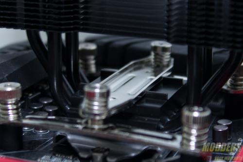
To fully secure the ETS-T40fit, the mounting bar is slid in the middle and secured to the mounting plate. The fan must be first removed in order to secure the heatsink to the mounting bars. The last step is of course installing the fan by just pushing it in place as the latches with take hold. The fan mount itself is attached to the fan via fan screws which require a Philips-head screw driver.
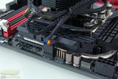
Do not forget to set the fan speed accordingly before installing the fan. For users with PWM motherboards, simply set the fan speed to maximum but for those who are going to plug the fan into a header with no PWM control, set the fan speed limiter accordingly.
NOTE: Enermax’ official statement on the Intel Skylake possible bending damage issue:
Enermax coolers are fully compatible with Skylake processors. In response to the recent reports concerning certain CPU coolers might damage the Intel Skylake processors; Enermax Technology Corporation would like to inform all of our customers that there is no evidence shows how cooler installation has any relations to the damage of the Skylake processors when users read and followed our installation manual. Nor would our brackets could harm the CPU during the PC system transportation, when system integrators have followed their own installation and transportation code of practice. For every cooler product, Enermax has taken a compulsory standard testing procedure for quality control, including mechanical load, vibration, aging, and compatibility fittings on various platforms. Once more, Enermax would like to reassure our customers that our coolers are fully Skylake compatible and thank you for your continuous supports.
Compatibility and Clearance Issues
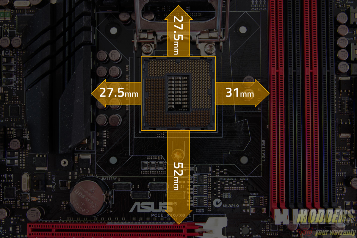
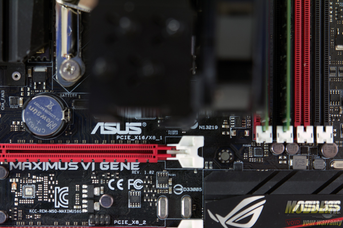
The test motherboard is an ASUS Maximus VI Gene micro-ATX motherboard and measuring from the edge of the socket (the gray plastic part), there is a 31mm gap between the CPU socket and the first DIMM slot as well as a 52mm clearance between the CPU socket and the topmost PCI-E x16 slot where the graphics card is installed:
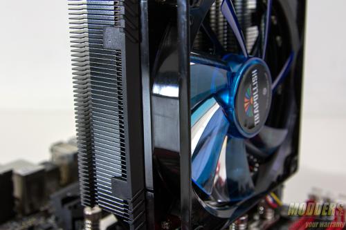
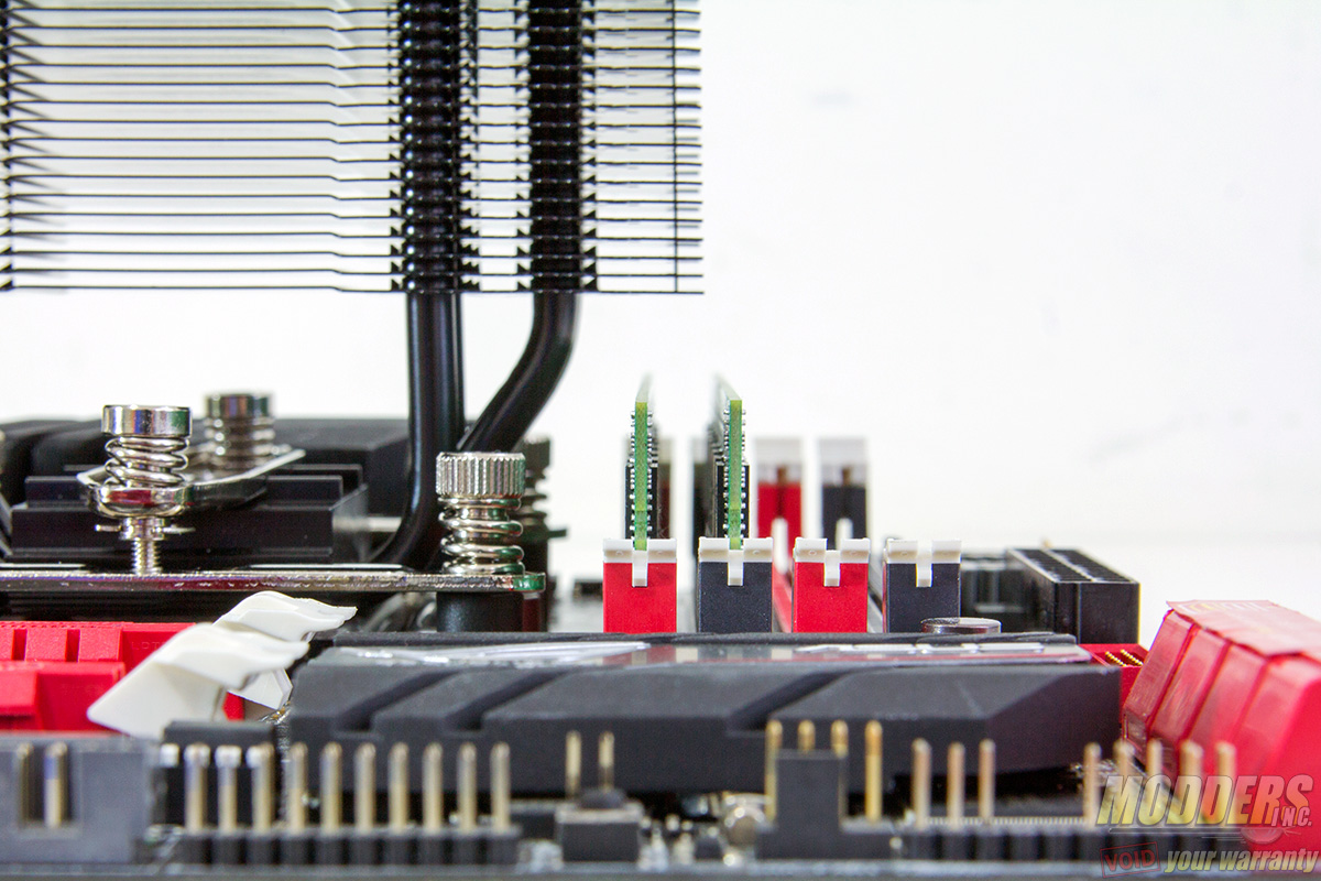
Because of the slim design, obviously there is a lot of space for DRAM clearance when mounted with the ventilation East-to-West but when positioned South-to-North, the first DIMM slot is limited to 39mm before it touches the bottom aluminum fin. The fan also has to be moved up slightly as installing the fan flush to the top aluminum fin will limit the clearance to only 28.7mm.
Obviously this is only a clearance issue when the ETS-T40fit is mounted in South-to-North orientation. The PCI-E also poses no clearance issue when mounted in East-to-West orientation and obviously there are plenty of space for graphics cards on the PCI-E x16 slot if mounted in South-to-North orientation.
