ECS Durathon 2 Z270H4-I Motherboard Review
A Closer Look at the ECS Z270H4-I Motherboard
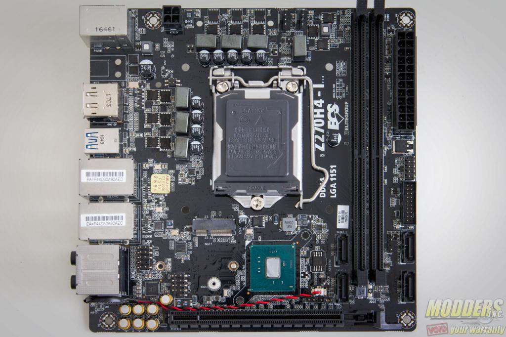
The ECS Z270H4-I supports the latest Intel 7th generation Core “Kaby Lake” processors as well as Intel 6th generation “Skylake” processors. The color scheme is mostly black with white PCB print.
Clearance and Heatsinks
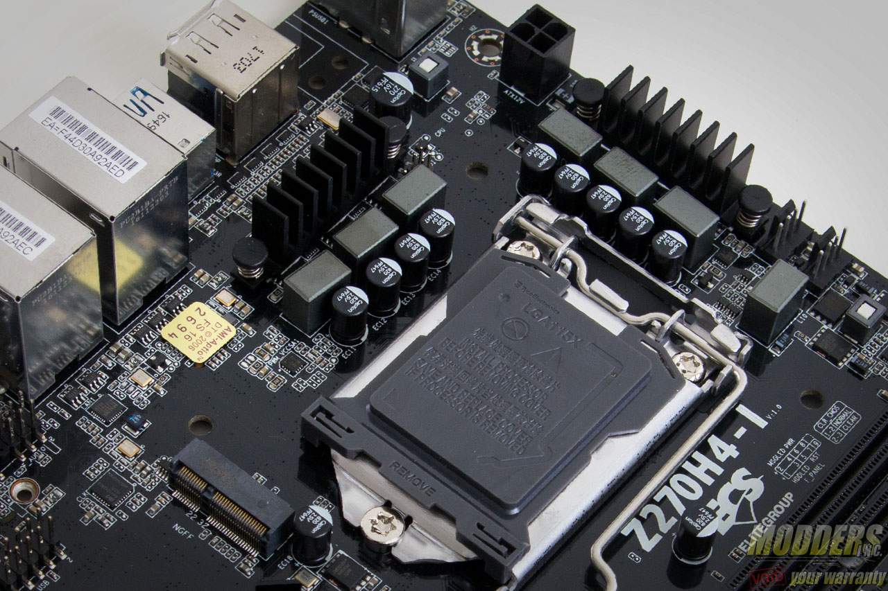
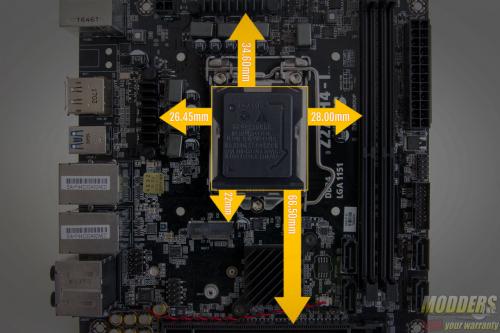
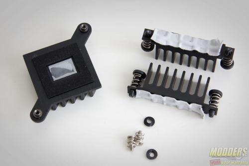
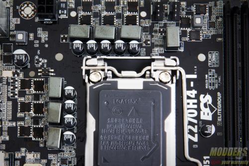
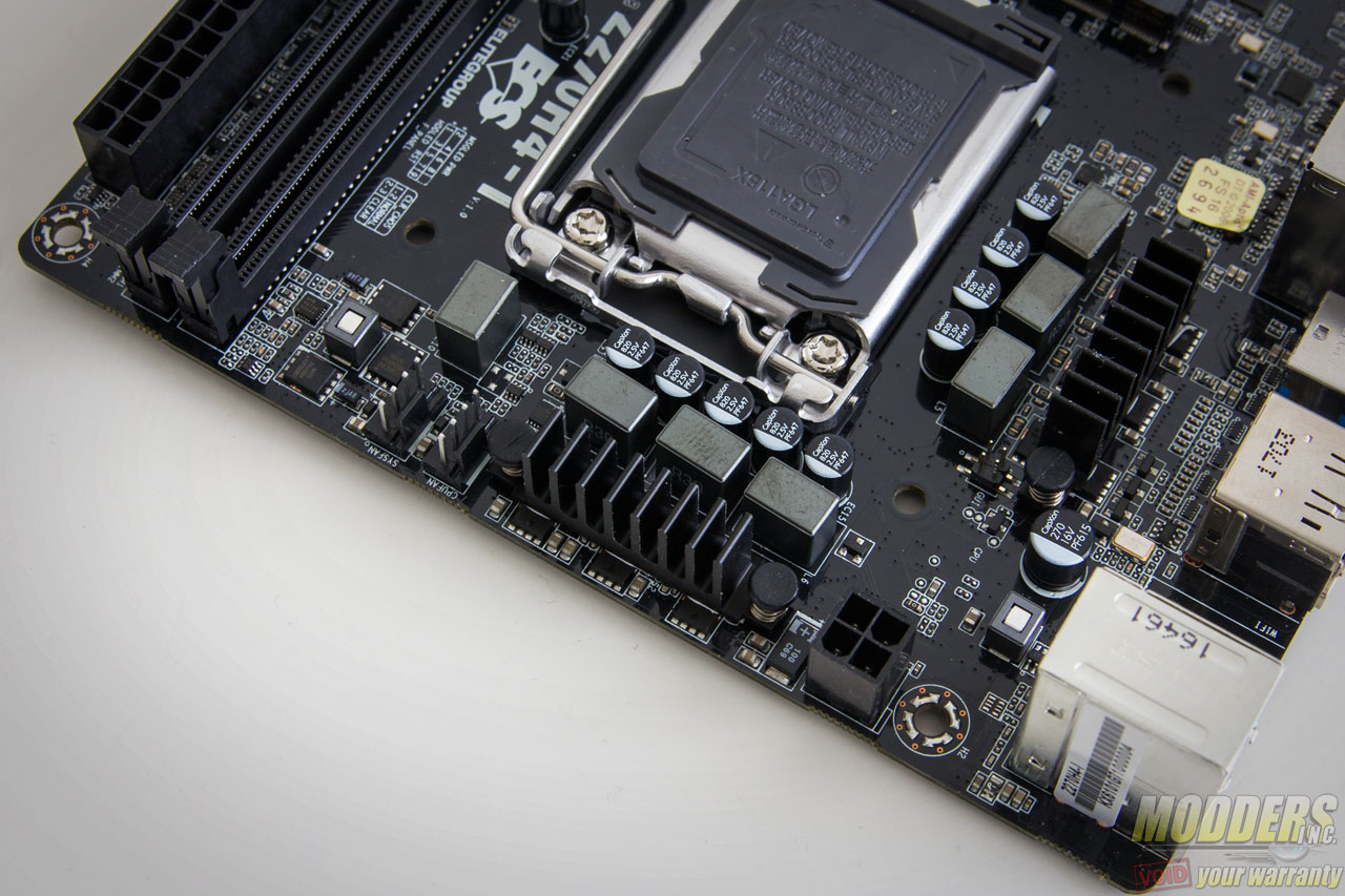
Even though the promotional photos show no heatsinks on the VRM MOSFETs, there two pieces installed for the CPU. These use simple spring-loaded push-pins while the chipset heatsink is held in place by spring-loaded screws at the back. The heatsinks are also all quite small and low profile, so they don’t particularly pose any notable clearance issues.
VRM Overview
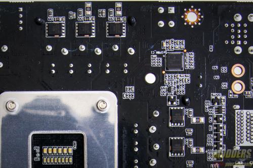
The main PWM is an Intersil ISL69137, which is a highly flexible IMVP8 PWM controller. It can be configured with up to seven phases in total and it can be configured in a variety of combinations to serve a dual output multi-rail system, i.e. 6+1, 4+3, etc. On the ECS Z270H4-i, this is configured as a 3-phases for the CPU and 2-phases for the iGPU. Each phase has three Taiwanese NIKO Semiconductor PK650BA MOSFETs driven by an Intersil ISL6596. All the capacitors are Chinese CapXon solid capacitors with the exception of the audio subsystem which uses Nichicon MW series audio-grade capacitors.
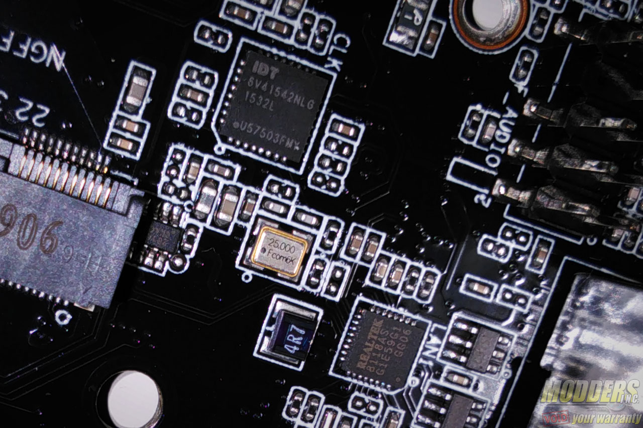
The VCCSA uses a single-phase buck with two NIKO semi PK650BA MOSFETs at the tail end of the VRM on the left side. The memory uses an Anpec APW8813 single-phase buck right beside the fan headers with two PK650BA and a NIKO semi PK6188. There is also an Integrated Device Technology 6V41542NLG external clock generator located right near the front M.2 for the flexible BCLK control.
The EPS12V connector only uses four pins instead of eight compared to other mainboards. The latch faces downward since the heatsinks are quite small anyway, although an upward facing latch is always better for easier unplugging.
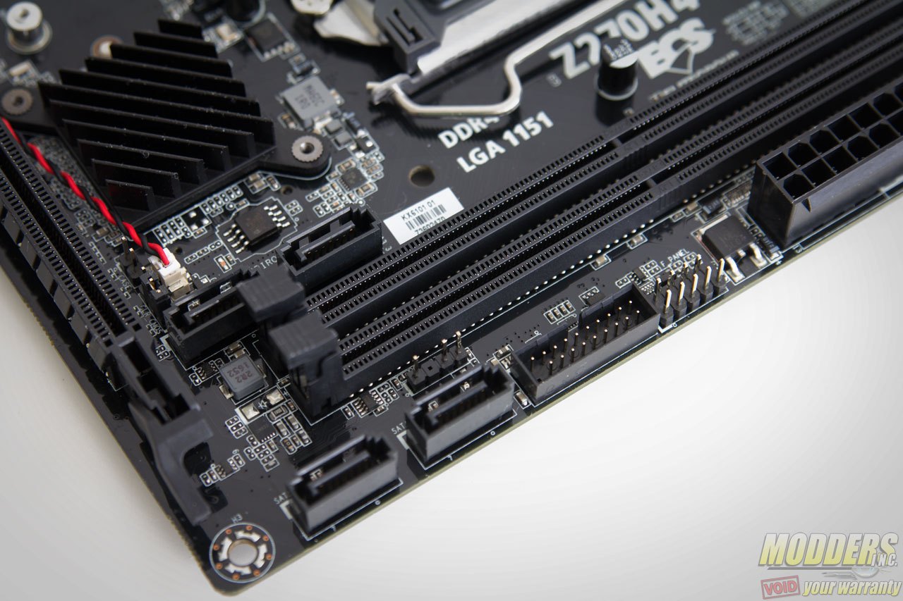
Two DIMM slots are available with a top and bottom latch, supporting DDR4 modules up to 32GB capacity and 3200MHz speed recommended by ECS. The 24-pin power is also located right at the right side edge with the latch facing outward.
Fan Control Options
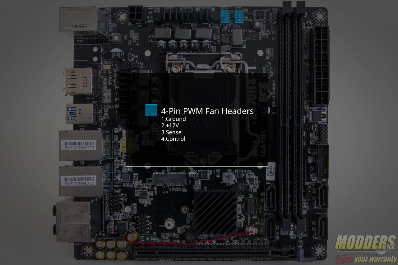
Only two 4-pin PWM fans are available on-board and they are both located right above the CPU socket.
Storage Options
Onboard storage begins with a pair SATA ports right below the 19-pin USB 3.0 front panel header. Two more SATA ports are available to the left side of the DIMM slots. All four face upward with the latch side facing the left.
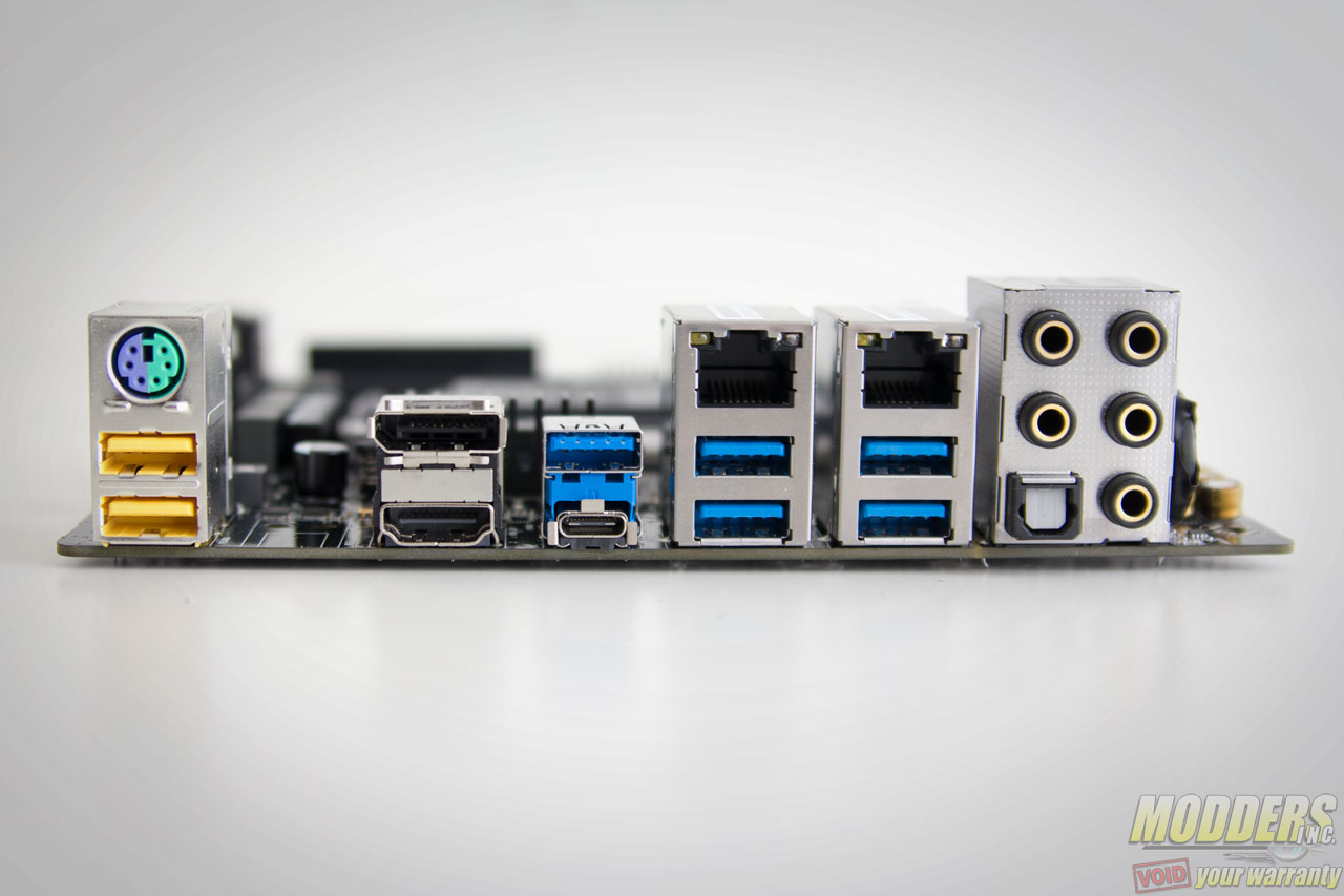
A 9-pin USB 2.0 header is available above the PCIe x16 slot close to the rear. Two additional USB 2.0 ports are available in the rear IO, with six USB 3.0 ports. One of these is a USB Type-C while the rest are Type-A. All of these are natively provided by the Z270 chipset.
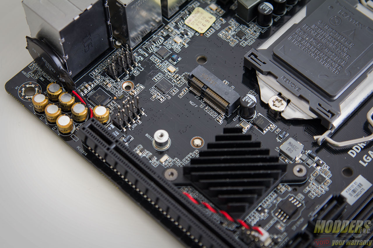
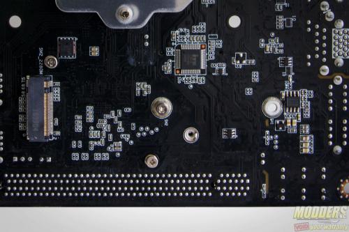
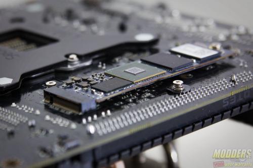
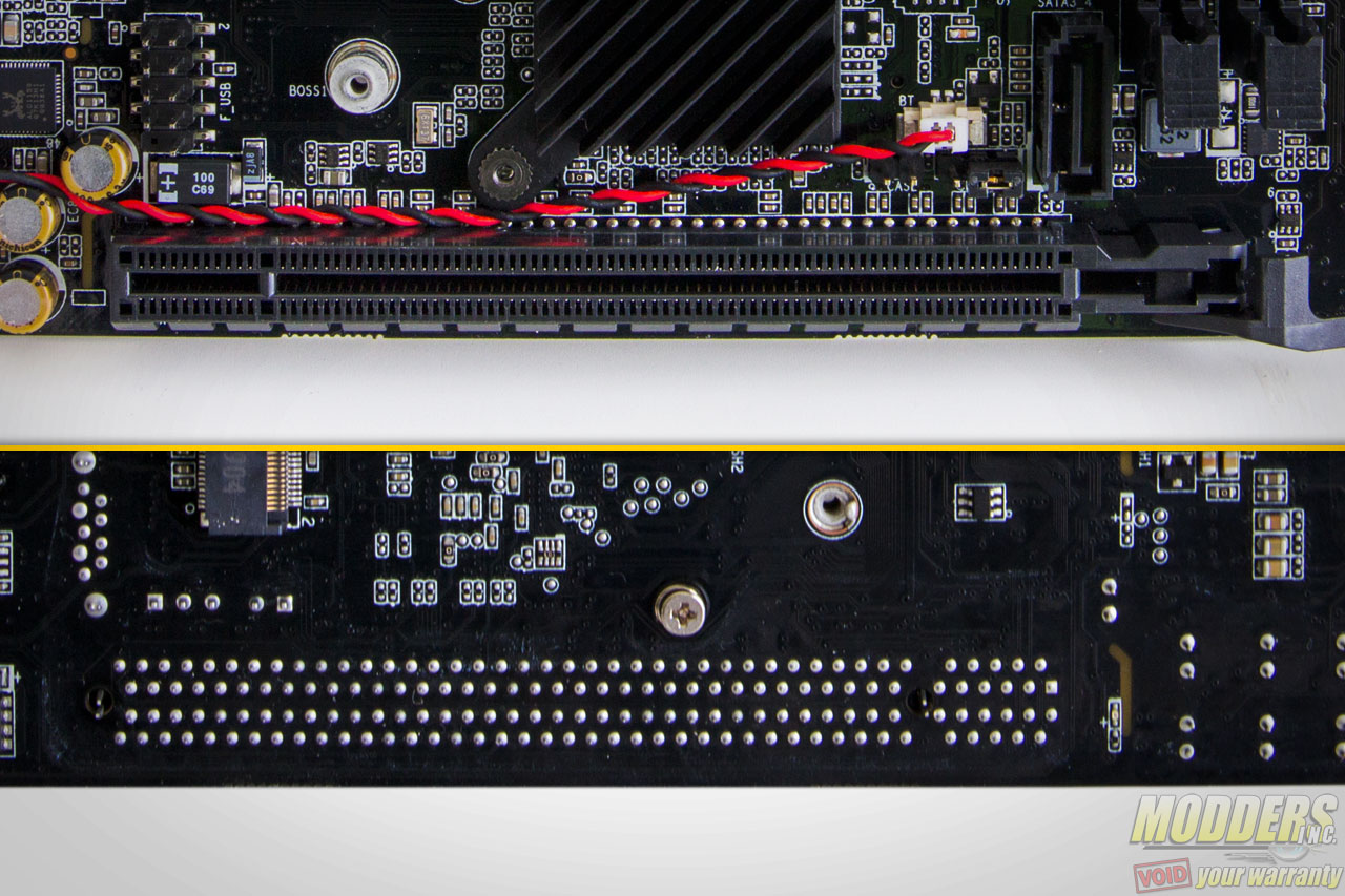
There are two m.2 slots available: one at the front and one at the back. The one on the front is for the optional WiFi/BT module only and the one at the back supports PCIe x4 32Gb/s M.2 SSDs that use either a 2242 form factor or 2280 form factor. Since it is located in the back, some SSDs with an additional heatsink might not be able to be installed unless there is an opening on the motherboard tray for it.
A Nuvoton NCT6779D SuperIO is responsible for most of the monitoring functions as well as the PS/2 function located in the rear. Unlike the X370 chipset, the B350 chipset has no PCIe x16 bifurcation capability so there is no SLI support, however CrossFire is still supported, albeit limited to PCIe x4 bandwidth and is conditional since the second slot shares bandwidth with the Ultra M.2 slot. Intel Optane products are supported.
The ITE IT8613E SuperIO is also located here in between the rear socket and the M.2 slot. This SuperIO is responsible for the PWM fan control, hardware monitoring, and rear IO PS/2 connector.
Expansion Slots
Expansion slot distribution is as follows (in order top to bottom):
- PCIe 3.0 x16 via Intel CPU
There is only one expansion slot since it is a mini-ITX motherboard.
Audio Subsystem and Rear IO
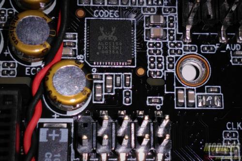
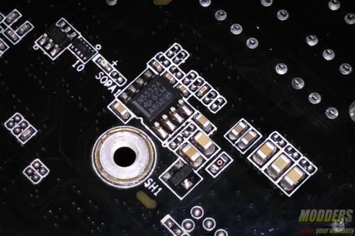
The audio subsystem is isolated (the partition actually lights up as a red LED when the system is powered on) and has a Realtek ALC1150 HD audio codec which utilizes Nichicon MW series electrolytic audio capacitors. In terms of audio output at the rear, there are five configurable analog audio jacks with one optical. The circuit also uses a Texas Instrument NE5532 OpAmp for driving headphone outputs.
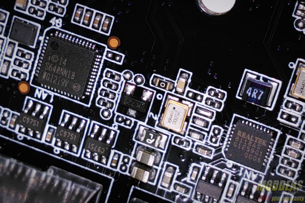
Networking options are provided by an Intel i219-V “Jacksonville” Gigabit LAN PHY and a Realtek 8118AS “Dragon” Gigabit LAN PHY. ECS is actually the first motherboard to use these Realtek Dragon before in their Z170 motherboards as an alternate to Killer NIC options. In terms of on-board display outputs, there is an HDMI 1.4 port, and a DisplayPort.
Wi-Fi Antenna Installation
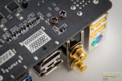
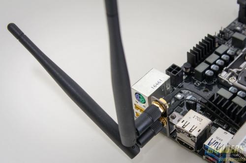
To install the antenna at the rear, use the two provided screws to secure the antenna mount from the bottom. The antenna itself, screws on and can be positioned to any angle.
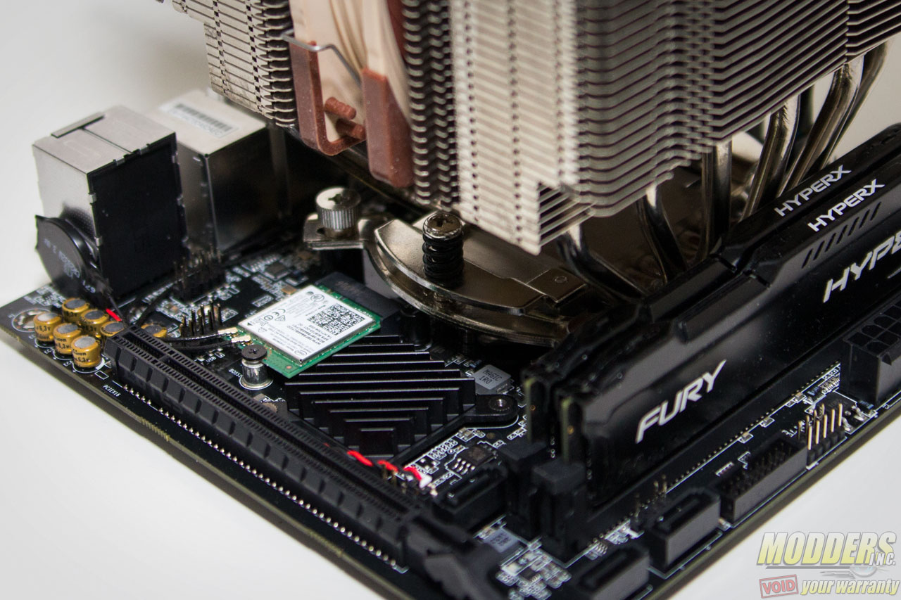
Before installing the WiFi/BT module, secure the antenna connectors first to the module then plug the module into the M.2 slot. With the video card taken out, it is actually possible to install an M.2 device in the slot with out removing the CPU heatsink. In the photo above, Noctua’s flagship NH-D15 CPU cooler is installed as a demonstration.
