ECS LEET Z170-Lightsaber Review: A Cut Above
A Closer Look at the ECS LEET Z170-Lightsaber Motherboard
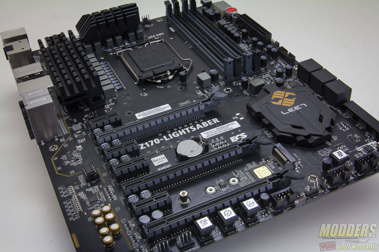
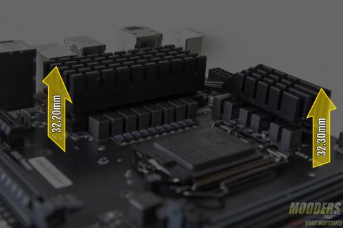
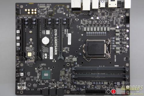
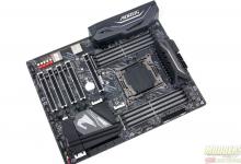
The ECS Z170-Lightsaber is rather conservative in its color scheme, having muted grays on a black PCB with a hint of gold from the L337 logo and the audio capacitors. It is conservative especially compared to many motherboards with extra covers, it is a bit more towards the functional side. The heatsinks in particular, are much more substantial than usual and has a very functional, air-flow friendly layout instead of being more stylized.
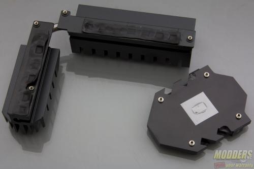
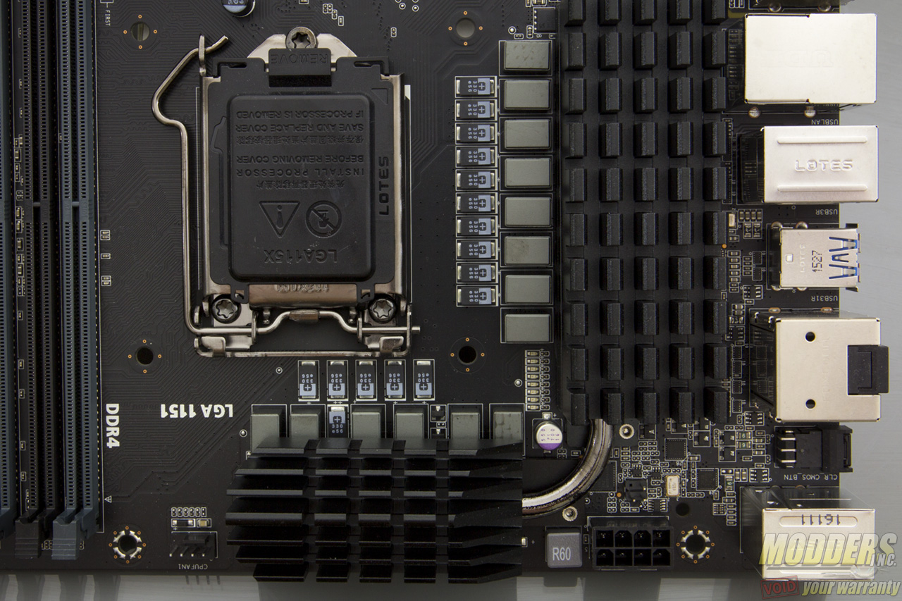
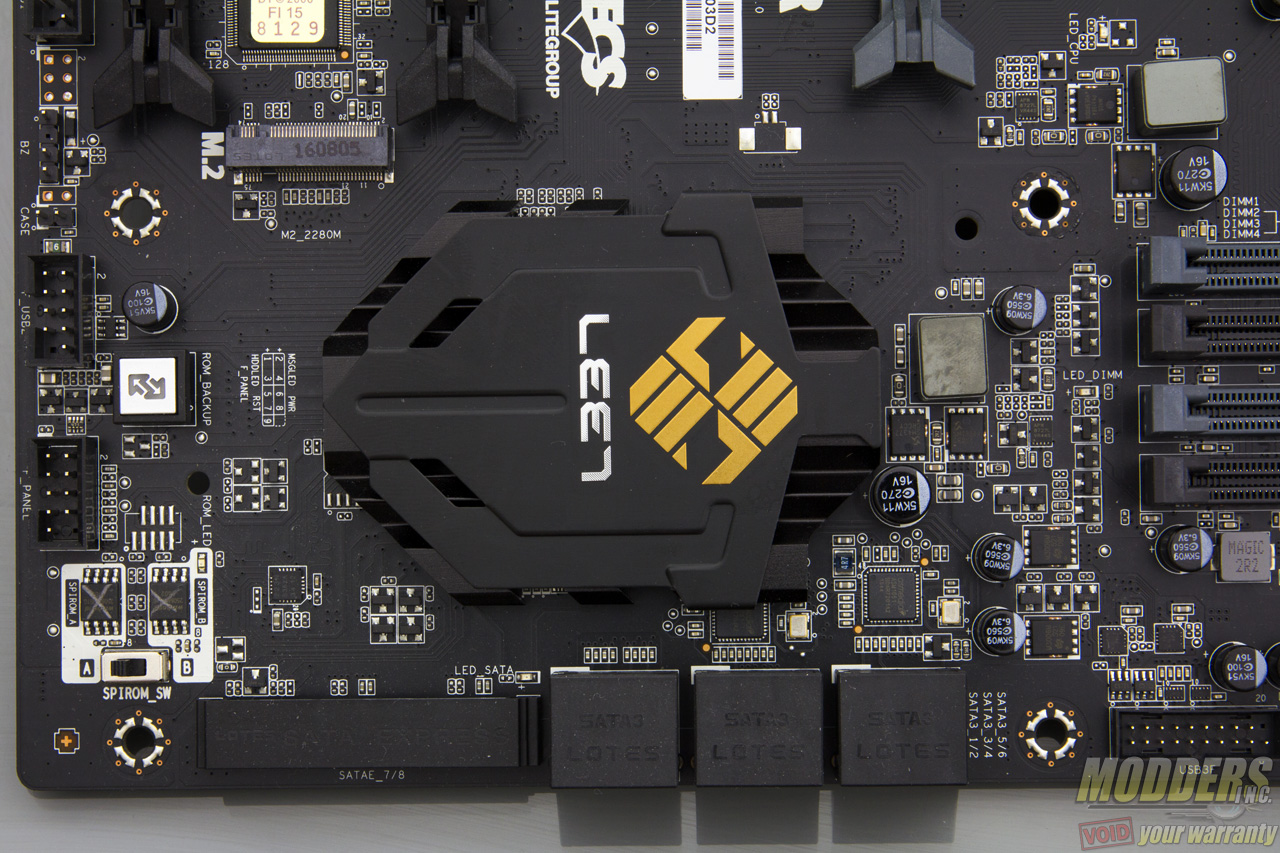
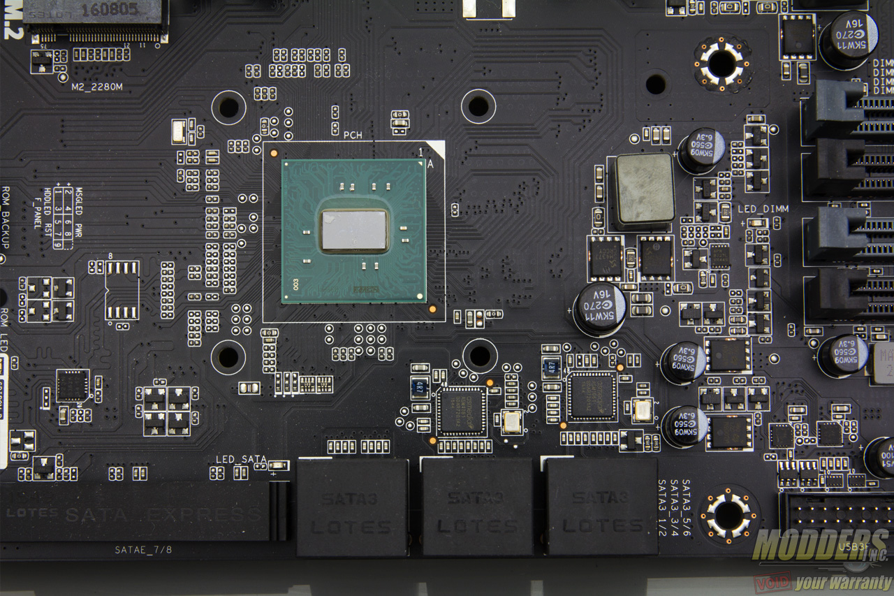
The VRM heatsinks weigh 185 grams while the Z170 chipset heatsinks weighs 59 grams. Both are held in place with spring-loaded screws in the rear with insulating film washers. The VRM heatsink is a two-stage design with the top part able to be removed from the contact area as it is secured by screws (underneath the black thermal interface material). This makes it easier to mod, repaint or replace with a custom design. It no longer has the extra gold plate hanging over from the Z170-Claymore however so that should improve thermal performance since the hot air pocket from the VRM can escape freely now. The chipset heatsink’s LEET cover plate is also held by screws from the side and can be easily modded out by users into putting their own emblem. The thermal interface material on the chipset is a thin gray paste which hardens when it dries out so it might take some wiggling to pry it off when removing.
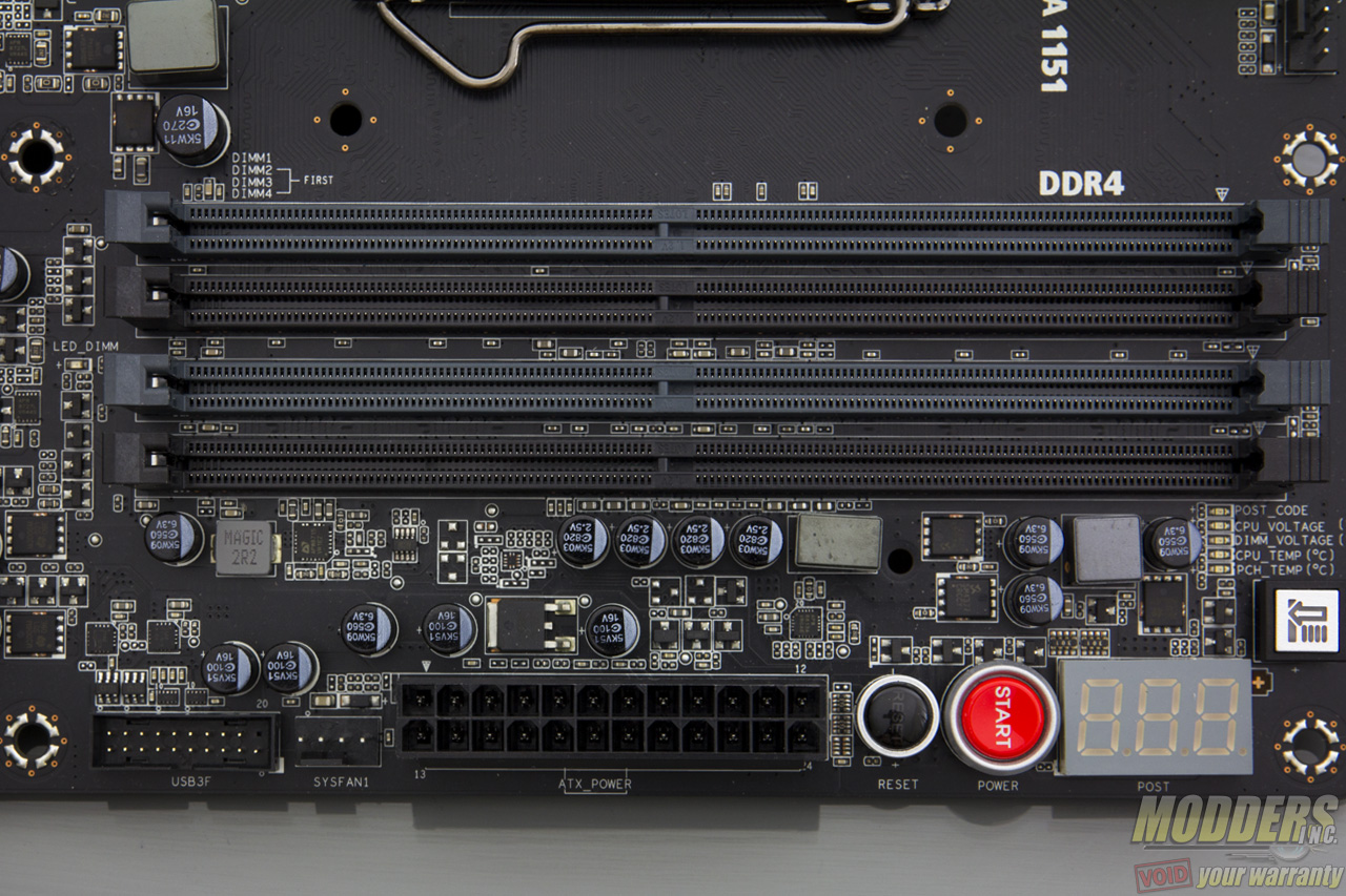
The 8-pin EPS12V power feeds the motherboard from the top with the latch facing upward. This is done to create more room since the heatpipe and VRM heatsinks are close to that area. With the latch upward, the user’s fingers have room to move around when plugging in or removing the 8-pin cable.
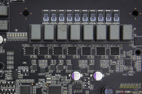
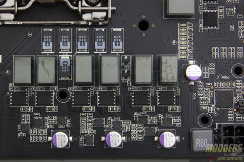
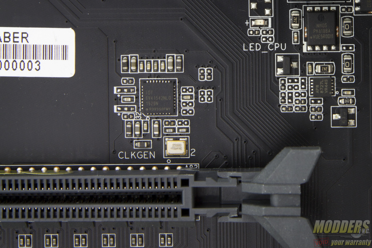
Two PWM controllers are present, both from Intersil: ISL69137 for the CPU and an ISL95853 for the secondaries. The ISL95853 is a 1+2+1 while there is no official available information yet on the ISL69137. This is most likely the same PWM controller seen on the previously reviewed Biostar Z170X-Gaming Commander (which was an IC sample since it was a pre-production model). It most likely is configurable up to 4 or 5 phases (4+1 or 5+1). The MOSFETs used on the Z170-Lightsaber are Sinopower SM7321 dual-channel MOSFETs. The signal is doubled from the PWM by an Intersil ISL6617A and each phase is driven by an Intersil ISL6596. Unlike the Z170-Claymore which uses Taiwanese Apaq capacitors for the entire board, the Z170-Lightsaber uses Tier-1 Japanese Sanyo POS-CAP Tantalum core capacitors for the output, Sanyo OS-CON solid capacitors for the power input and Apaq 5K solid capacitors are used for the rest of the motherboard with the exception of the audio area which uses top tier Japanese Nichicon MW-series audio electrolytics.
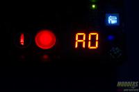
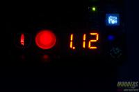
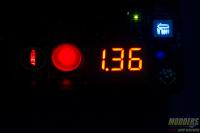
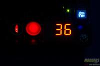
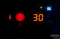
Four DIMM slots are available with an Anpec APW8813A single-phase memory controller using a pair of Sinopower SM4377 MOSFETs. On the top right corner are some helpful onboard features including a status view button with a 3-digit display, and onboard power as well as reset buttons. Unlike other motherboards which have a two-digit seven-segment LED displays, the Z170-Lightsaber has a three-digit display. This is because it does more than just show CPU temperature when the system is in operation or show POST codes while botting. With the status view button, users can cycle between five functions (in order): Post code, CPU voltage, DIMM voltage, CPU temperature and Chipset temperature (both temperatures in Celcius).
The 24-pin motherboard power header is directly underneath the on-board buttons and directly underneath that is a 4-pin system fan and a 19-pin USB 3.0 header from the Z170 chipset.
Four SATA ports via the Z170 chipset are available, two of which (SATA ports 7 and 8) can be used as a SATA Express port as well. SATA 3/4 and 5/6 are from two ASMedia 1061 taking up one PCI-E x1 each per pair of SATA ports.
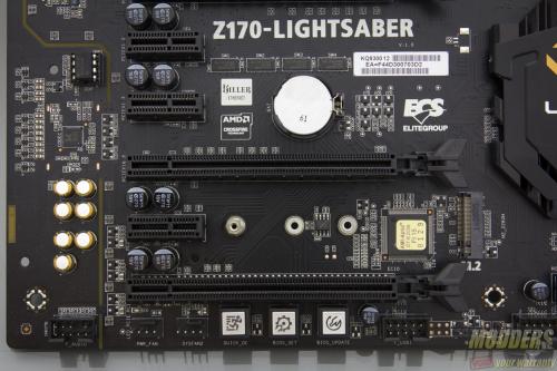
The single m.2 option resides in between the bottom two PCI-E x16 slots. This M-key M.2 supports both PCI-E and SATA devices and NGFF 2242, 2260 and 2280. Unfortunately, 110mm long devices are not supported since a PCI-E x1 slot is on the way, which will limit the storage size that can be utilized on the Z170-Lightsaber.
Two hardwired SPI flash are available and switchable for BIOS redundancy on the bottom right corner. An indicator LED is also present beside them as well as a convenient ROM backup button right above a 9-pin USB 2.0 header from the Z170 chipset. Another USB 2.0 header is available right in the middle bottom edge of the board as well. The front panel header bank is located right beside the two SPI flash ROMs and although they are not color coded, the pin-out guide is printed right above the ROM backup button directly below the chipset heatsink. This front panel header is only 9-pins because the buzzer header is separate and it is located right in between the two USB 2.0 headers with the case open header.
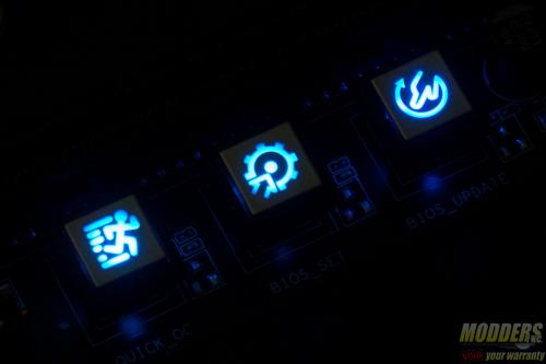
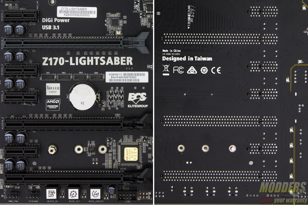
The rest of the bottom edge has a Quick OC button, BIOS set button and BIOS update button. The BIOS set button is used to enter the UEFI quickly. It will enter the UEFI on the next time the system boots. If pressed while the system is running, the system will keep running. If pressed while the system is in standby, it will enter UEFI mode once the system is turned on. The Quick OC button automatically overclocked the Intel Core i7-6700K processor installed to 4.3GHz with 1.275 Vcore.
Expansion slot distribution is as follows (in order top to bottom):
- PCI-E 3.0 x1 via Z170
- PCI-E 3.0 x16 via CPU (x16, x8 when slot 5 is populated)
- PCI-E 3.0 x1 via Z170
- PCI-E 3.0 x1 via Z170
- PCI-E 3.0 x16 via CPU (x8)
- PCI-E 3.0 x1 via Z170
- PCI-E 3.0 x16 via Z170 (x4)
AMD Crossfire is supported but NVIDIA SLI is not (ECS would have to pay to get license from NVIDIA).
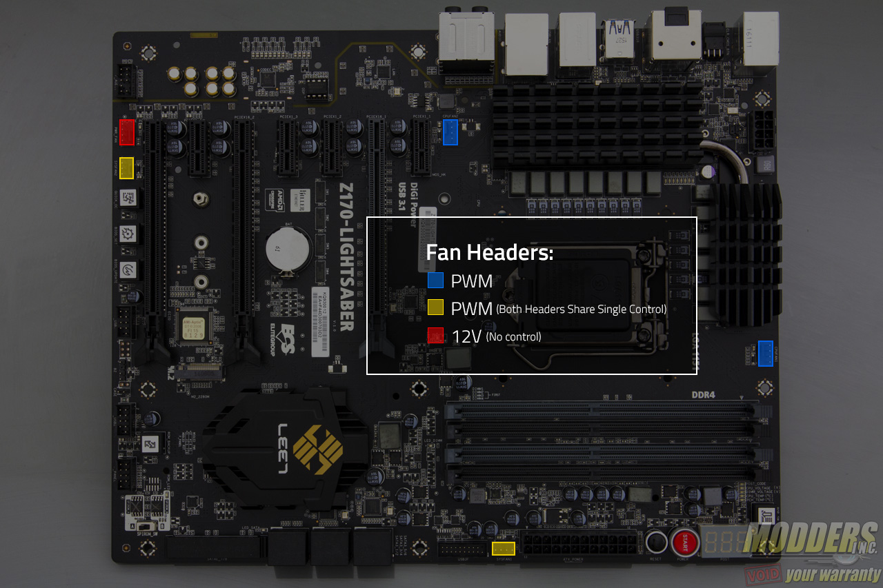
There are five fan headers in total, all are 4-pin physically but only three are individually controllable PWM headers: CPUFAN1, CPUFAN2 and SYSFAN1. SYSFAN2 is a mirror header with the SYSFAN1 and synchronizes whatever speed setting that fan header is using. The last fan header beside the SYSFAN2 is the PWR_FAN which runs at a constant +12V and cannot be controlled.
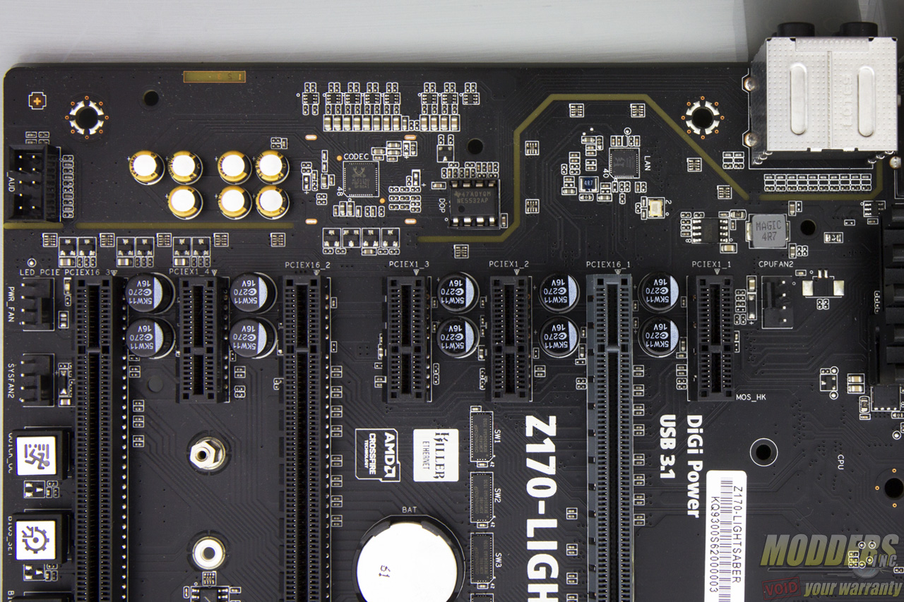
The audio subsystem is physically isolated from the rest of the PCB and audio is handled by a Realtek ALC1150 HD Audio codec. The ALC1150 has 115dB front DAC and 96DB DAC for the rest of the output channels and supports 24-bit playback/line in. This audio subsystem lights up with RGB LEDs lined up at the rear of the PCB that shine through the isolation border. The color option for this area can be adjusted inside the UEFI only. Nichicon MW series audio capacitors are used for filtering in this area with a Texas Instruments NE5532 op-amp for the rear IO audio output using a non-soldered PDIP so users can swap it out if they wanted.
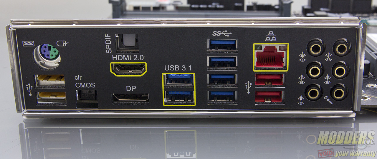
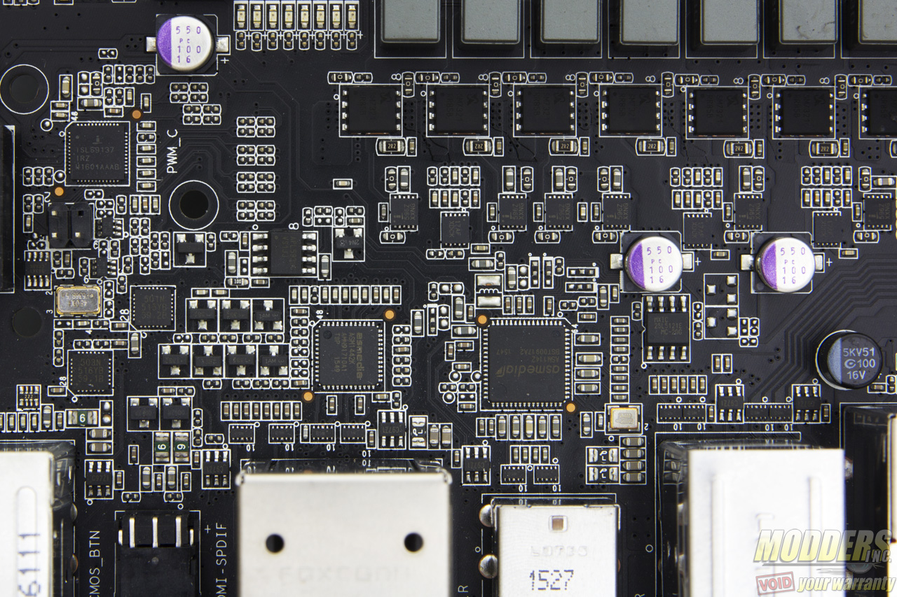
A Killer E2400 NIC is used for Gigabit Ethernet and right below the RJ-45 port at the rear IO are two red USB ports with the dedicated stepped down power from the PSU input to +5V. Use these ports if using a USB DAC or any device that requires steady power. The yellow ports are the “gaming” designated USB ports with 1000Hz polling rates and the legacy PS/2 connector is available beside them as well since they are still used for poll-less input. The rest of the natively provided USB ports in the rear also include four USB 3.0 ports. Two are USB 3.1 gen 2 Type-A ports in between the four USB 3.0 bank and the display output bank. These USB 3.1 ports are provided by an ASMedia ASM1142 PCI-E bridge, able to take a pair of PCI-E gen 2 or a single PCI-E gen 3 and provide two downstream USB 3.1 ports with up to 10Gbps bandwidth.
For display output of on-board graphics, ECS provides a DisplayPort as well as HDMI 2.0 with the help of an ASMedia ASM1442K level-shifter. Above the HDMI port is the optical audio out.
For the rest of the rear audio output, there are six configurable analog audio jacks having gold plating on the connector end and having uniformly black colored receptacles. These connectors are labeled only for their default input or output tasks on the IO cover. The three jacks (from top to bottom) on the left side are the center/subwoofer, back surround and side surround, while the three jacks on the right side however are the line-in, front out and microphone. Lastly, there is also a clear CMOS button for would be overclockers or system tweakers.
