Cryorig H5 Ultimate CPU Cooler Review: A Matter of Perspective
Installation of the CRYORIG H7
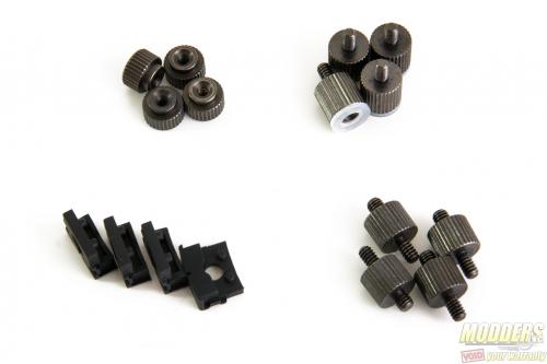
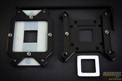
As always before starting, make sure that all the parts listed in the user’s manual are included in the package and lay them all out for easier installation. Intel and AMD use different sets of backplate and mounting bracket combos but otherwise, the steps are similar with the exception of the variable post on the non-Intel LGA2011 installation (LGA2011 does not require backplate) and having mounting post position dependent orientation.
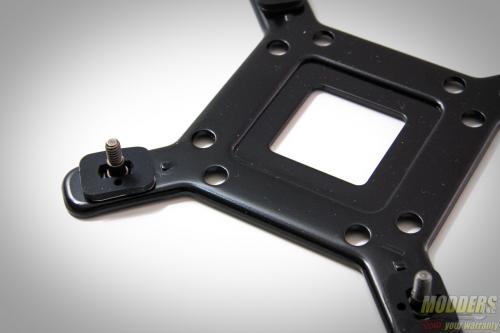
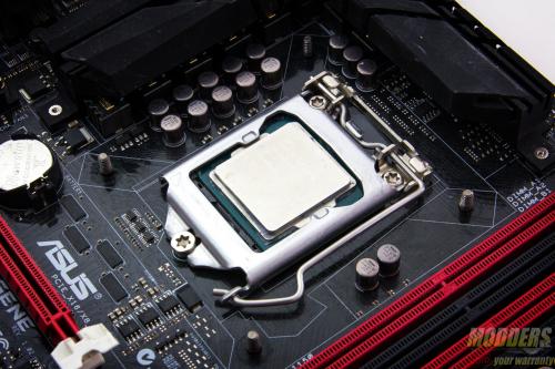
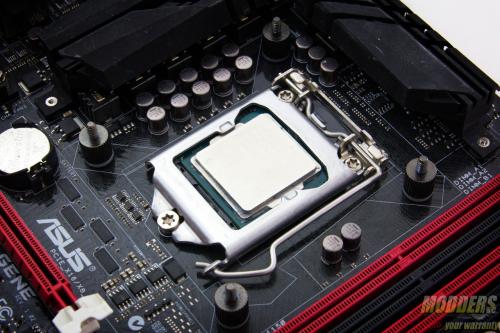
For Intel systems, the backplate has three different positioned holes to accommodate LGA775, LGA1366 and LGA115x sockets. Because people have been asking, yes LGA115x covers every single socket including LGA1151, LGA1150 and LGA1156 because the mounting hole distance is exactly the same for all of those models. By default, the post is positioned for LGA115x motherboards but if users want to install on an LGA1366 motherboard, the posts have to be moved to the outer area while LGA775 installation requires the posts to be moved inwards and for the extra square piece from the accessory pack to be fitted in the middle.
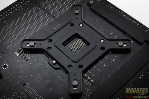
The backplate can be positioned in any orientation. There is padding on each of the corner posts for insulating the motherboard from the metal backplate. For AMD users, CRYORIG provies a replacement backplate with the posts integrated as well.
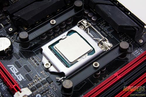
Once the backplate assembly is in position, attach the stand offs and thumbscrew them in place. These stand offs are pre-insulated on the female side so as not to scratch the motherboard surface when tightened. The contact will not be completely tight once fully screwed in place to the backplate assembly. Place the mounting bar with the curve facing outward and the recess facing upward.
Like the backplate, the Intel mounting bar has three variable holes for LGA775, LGA115x and LGA1366 mounting. Depending on how you want to orient the CRYORIG H5, position the mounting bars appropriately. AMD users follow the same steps except the mounting bar is a single piece and only installs one way. The heatsink can be installed in both North/South or East/West orientation however as there are supporting mounts for those positions.
Once the brackets are held in place with more thumbscrews, there is in fact some wiggle room and it is part of the mounting design. When the heatsink is fully secured, there will be no extra movement from the mounting kit.
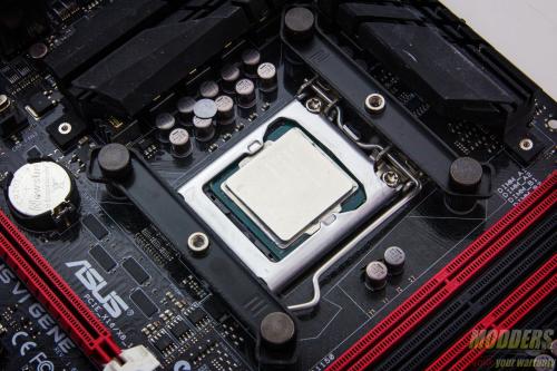
Apply thermal compound on the CPU socket and then place the H5 on top, with the integrated mounting mechanism aligned to the screw post threads. Use the bundled screw drive, drop it into the H5’s access screw holes at the top and partially secure each side in an alternate fashion partially for equal weight distribution until fully secured in place.
The nice thing about the CRYORIG H5 Ultimate mounting is that users do not need to remove the pre-installed fan when installing the heatsink. If it was removed for some reason, it is just a matter of latching the wire to the grooves on the side. The final step is to attach the fan wire to a header or any power source.
Clearance Compatibility
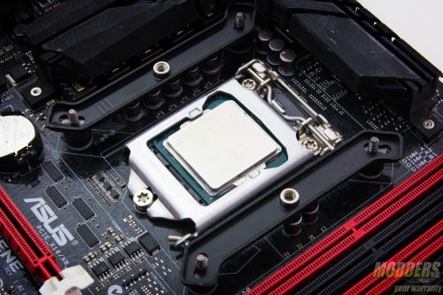
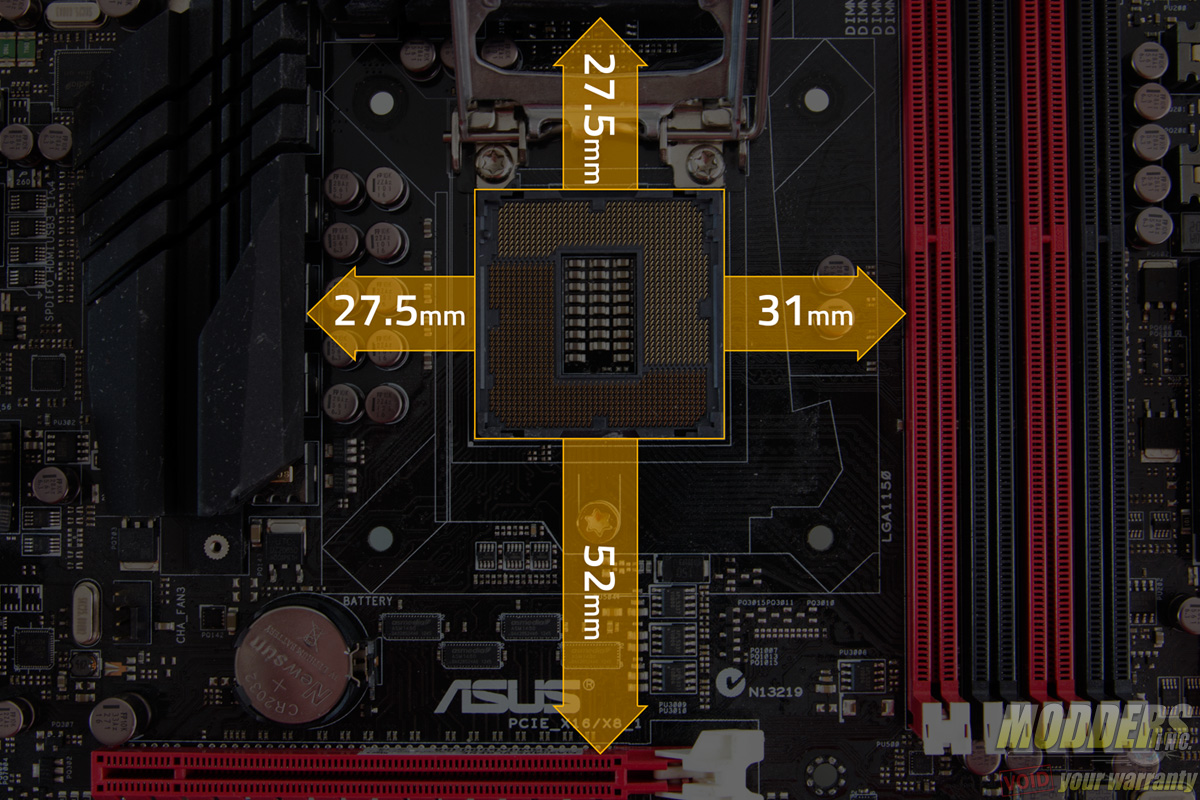
The test motherboard is an ASUS Maximus VI Gene micro-ATX motherboard and measuring from the edge of the socket (the gray plastic part), there is a 31mm gap between the CPU socket and the first DIMM slot as well as a 52mm clearance between the CPU socket and the topmost PCI-E x16 slot where the graphics card is installed:
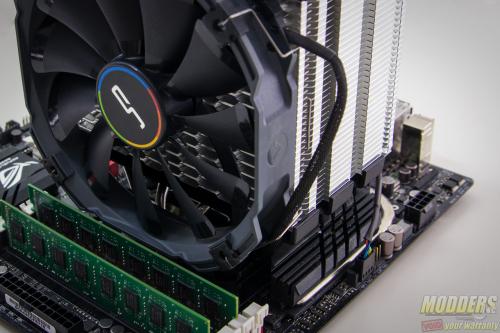
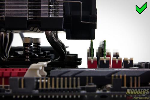
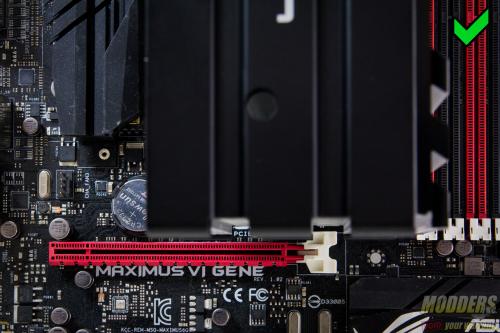
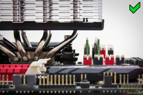
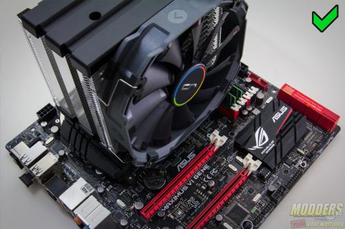
Installed in the default position with the intake beside the RAM slots shows zero problems with some room to spare for both PCI-E and RAM clearance. The fan overhangs over the first DIMM slot however but users can adjust the fan upward to provide more clearance for taller heatspreader modules if necessary. The second DIMM slot is completely obstruction free. Space is also tight for the PCI-E x16 slot but has no problem installing a video card without being obstructed.
The same can be said for vertical position with the intake fan at the bottom. Although the first two DIMM slot is obscured for RAM modules taller than 35mm. The fan might also have to be moved up a bit to provide more clearance as well.
