Cougar 700K Keyboard: The Audacity of Functional Design
Disassembly and Modding Options
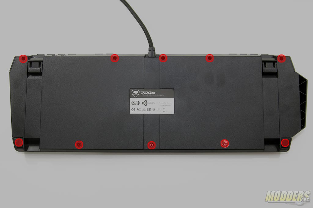
Disassembly begins by removing 10 screws at the rear. This will allow the modder to remove the two top plastic edge on the other side. One screw is underneath the round warranty sticker at the bottom but there is not much glue here and you can lift this sticker slightly with an X-acto knife without damaging the sticker. Two outer edge screws are located underneath the rubber pads at the bottom (some glue might be needed to reapply these again once removed)
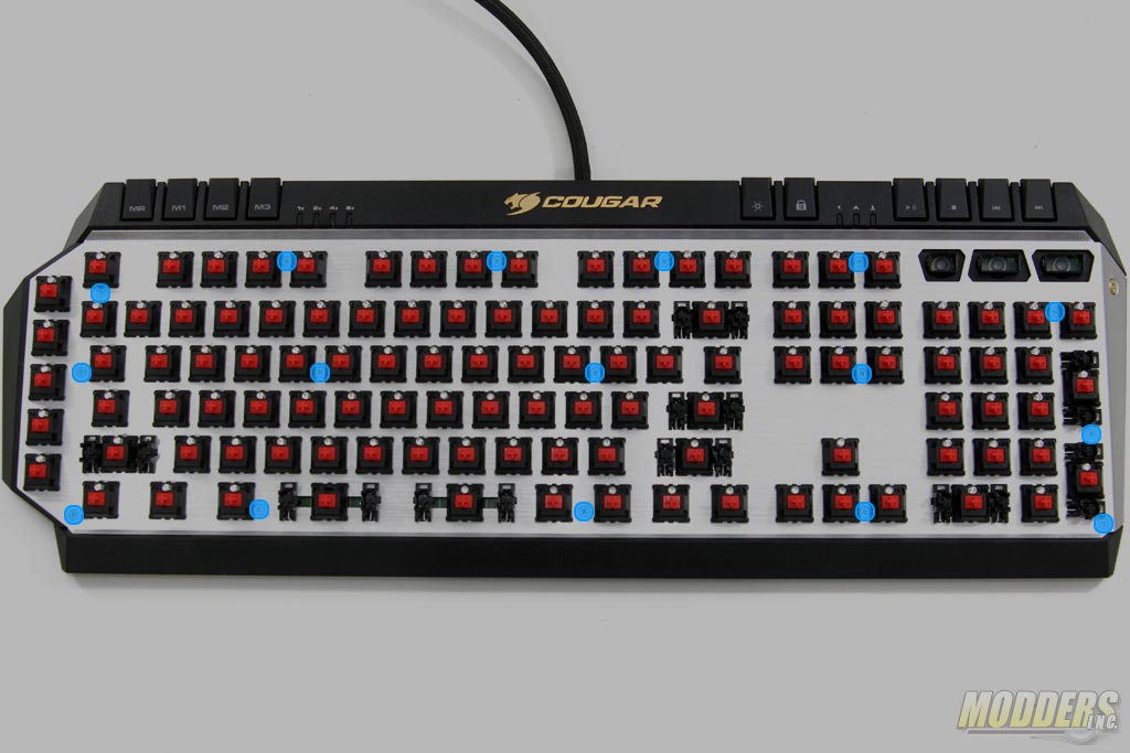
You can pop-out the top and bottom plastic edges once you remove the back screws but to expose the PCB, you have to remove a lot of screws at the top plate first (marked blue in the image below).
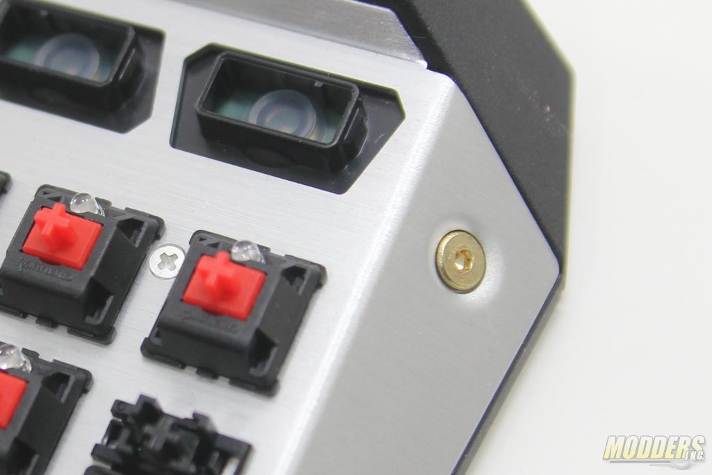
While all the screws require a Phillips-head screwdriver, there is a 2mm brass hex screw holding the plate in place that needs to be removed as well.
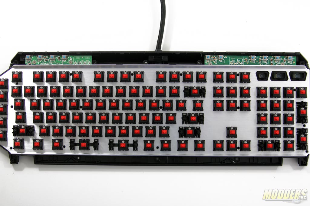
This is what the keyboard looks like with the plastic trim popped out and all the screws removed.
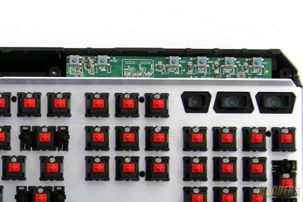
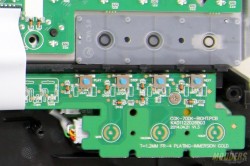
These are actually high-quality square switches used on the multimedia, MR, profiles, winlock and backlight toggle key and takes a bit of force to actuate (I ran out of American nickels to measure but I’ll get back to you, these Canadian nickels don’t weigh the same). Also nice to see a diode per key even here.
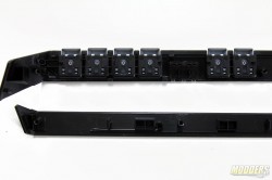
This is what the top and bottom trim looks like. You can remove them without removing the individual keycaps thankfully. Watch out for the transluscent LED diffuser though as that might fallout as it just snaps into place.
Full back main PCB view. Two of the minor PCBs are connected via ribbon cable and the third is the pass-through PCB not data-connected to the main PCB.
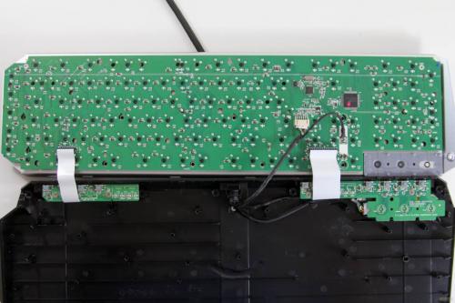
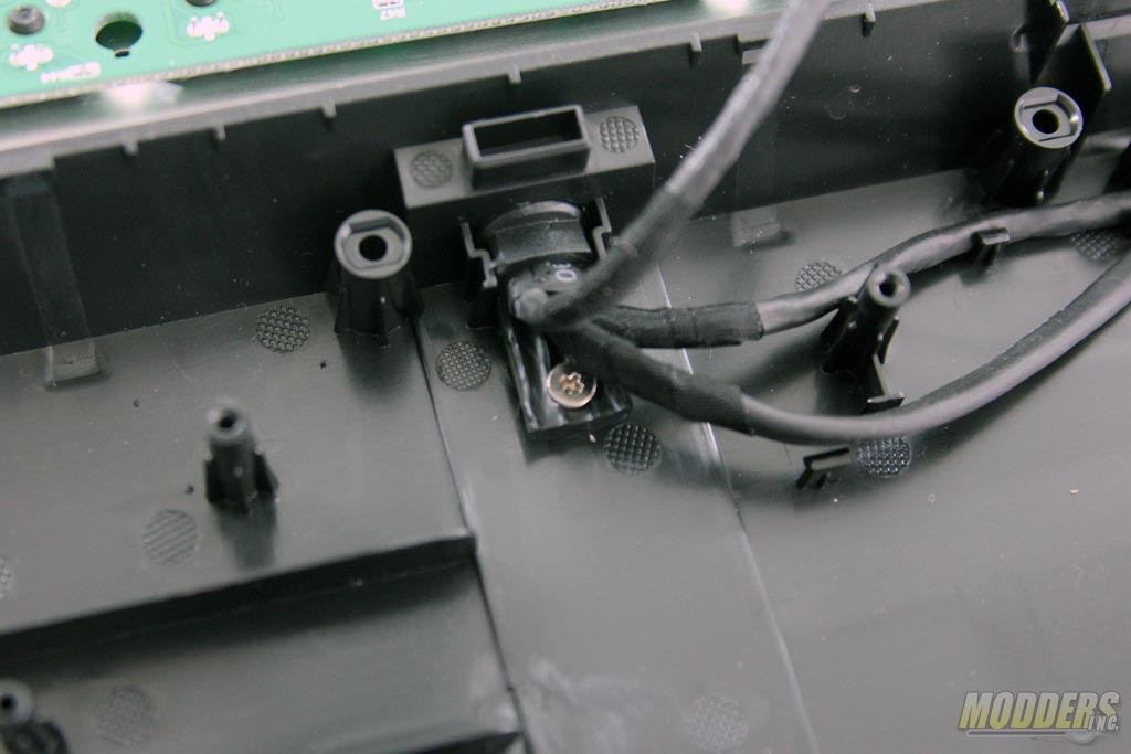
To completely free the PCB from the housing before modding, you have to remove this screw first holding down the cables.
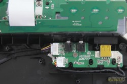
A view of the multimedia and volume control keys. The audio and USB passthrough are on their own PCB directly underneath as well.
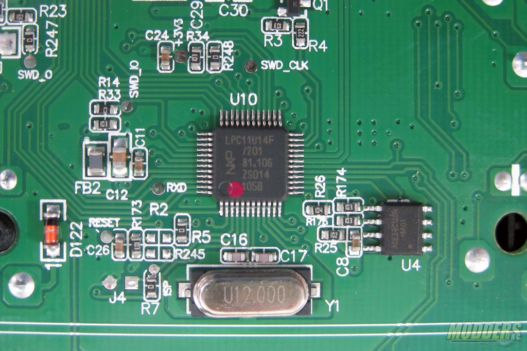
This little guy is an NXP LPC11U14/201 CORTEX-M0 Processor, responsible for handling all the major functions of the Cougar 700K. The SOP8 package you see close to it is the Ace Technology ACE24C128B 128kbit IIC Serial EEPROM for Firmware storage.
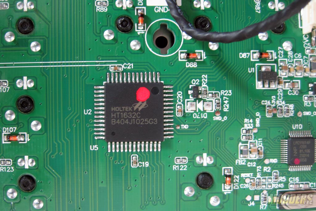
This big guy is the Holtek HT1632C LED driver, obviously responsible for the more elaborate LED related functions.
