Corsair Dominator Platinum RGB DDR4 Memory Review
A Closer look at the Corsair Dominator Platinum RGB
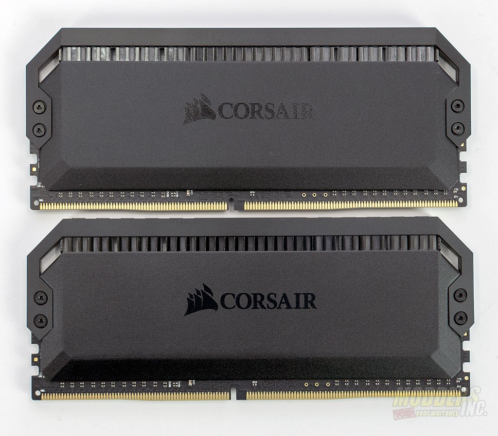
On one side of the memory module, the only thing you’ll see is an embossed Corsair logo on the heat spreader. The heat spreaders are made of aluminum. The top bar is held in place by four Torx head screws at each side of the module. At the top of the module, you’ll see slats with a translucent plastic diffuser behind them. This is used to diffuse and direct the lighting from the LEDs
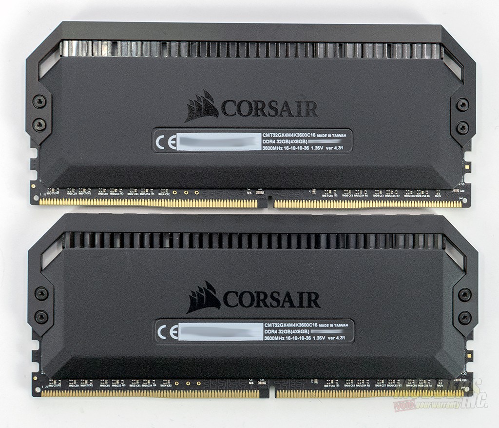
On the opposite side, you’ll find the same embossed Corsair logo and the specification sticker. This sticker will give you the model number, capacity, speed, and the serial number of each memory module. In this case, the timings are 16-18-18-36 with 1.35v.
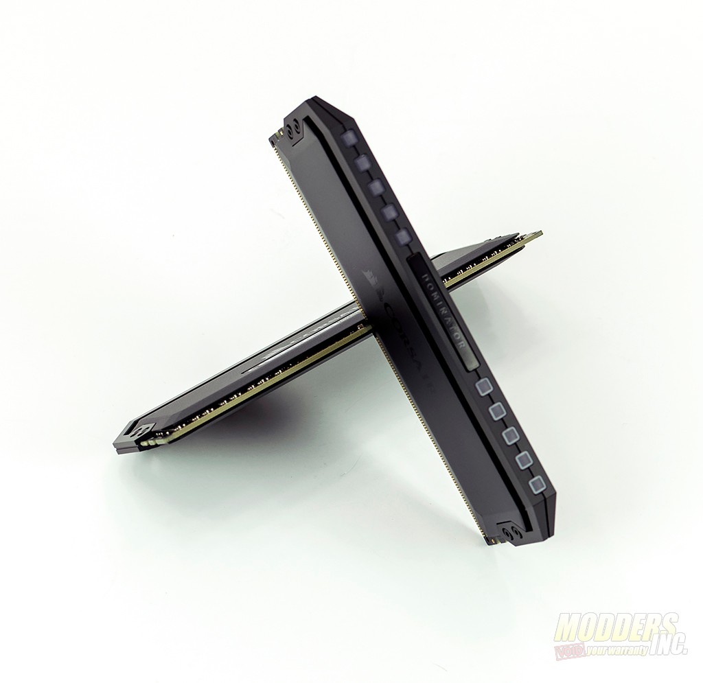
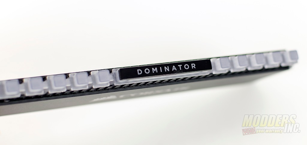
At the top of the Corsair Dominator Platinum RGB modules, you’ll find five square holes at each end of the module that house the top part of the diffuser.
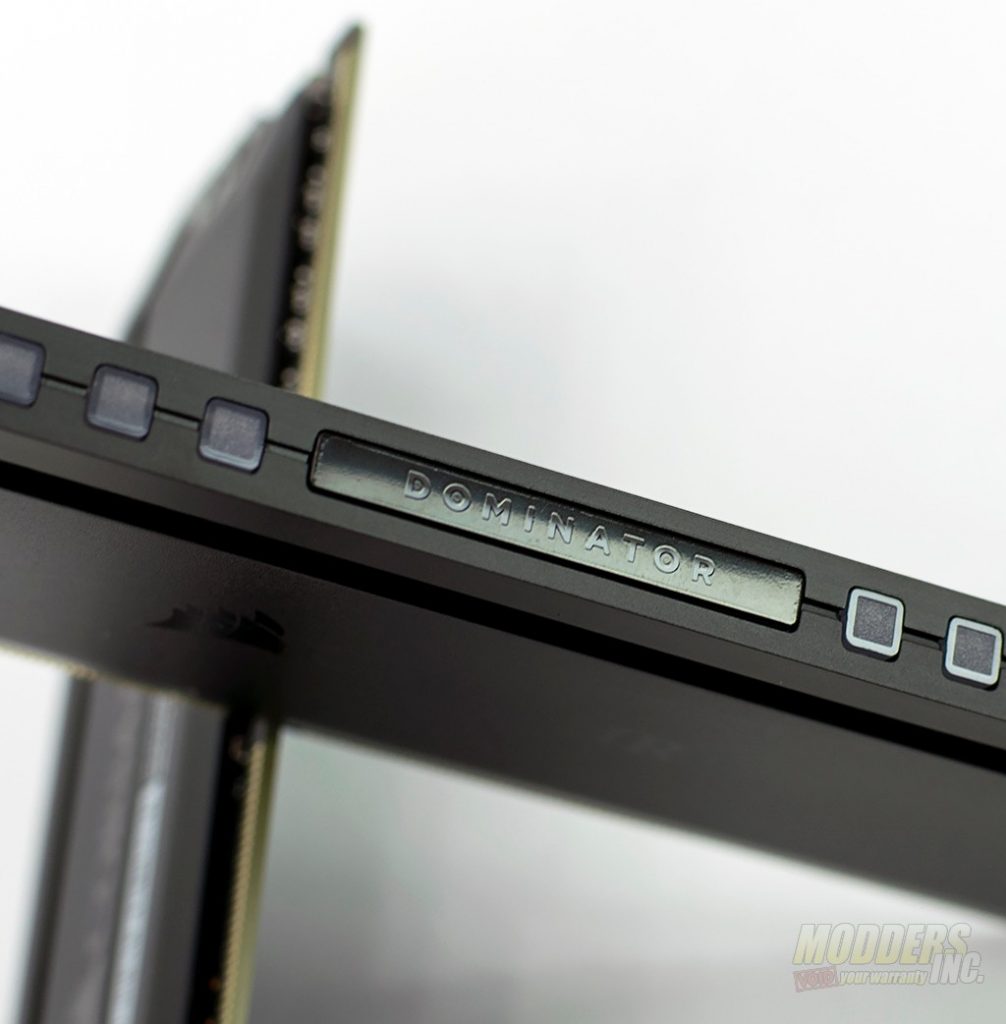
In the center of the module, you’ll find the DOMINATOR logo.
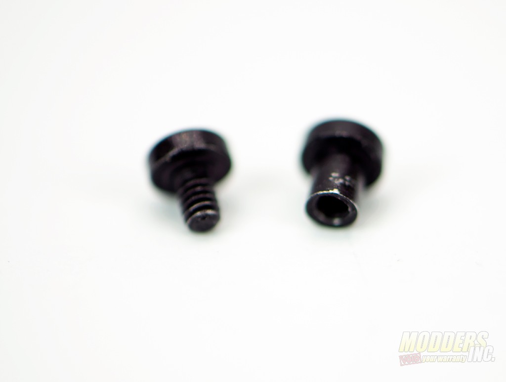
There are four fasteners to remove when tearing down the Corsair Dominator Platinum RGB. One side of the module is actually a screw and the other is a nut.
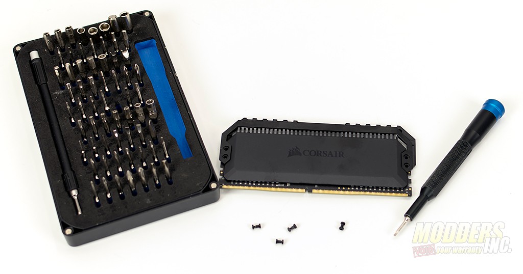
Once all four sets of fasteners have been removed, the top bars (one for each side of the module) come off with ease.
With the top bars removed, you can get a clear view of the diffuser underneath.
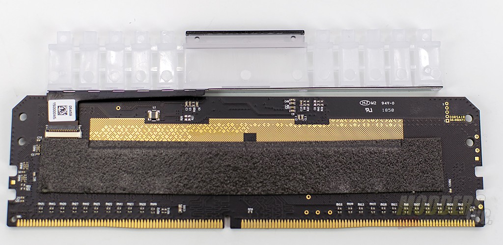
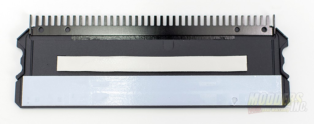
Both aluminum covers on the Corsair Dominator Platinum RGB are identical. While only one side of the PCB is populated, each heat spreader has thermal pads. On one side, the pads sit on top of the memory chips and on the other it sits directly on the PCB.
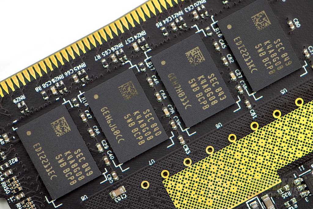
The PCB is populated with ICs on only one side. Corsair uses Samsung B-Die memory modules and lately, Samsung’s been the choice for higher speed memory. The Samsung K4A8G085WB BCPB B-die is used in a lot of memory modules from practically every manufacturer and with speeds reaching up to 4600 MHz with XMP profiles. This kit here is rated for 3600 Mhz.
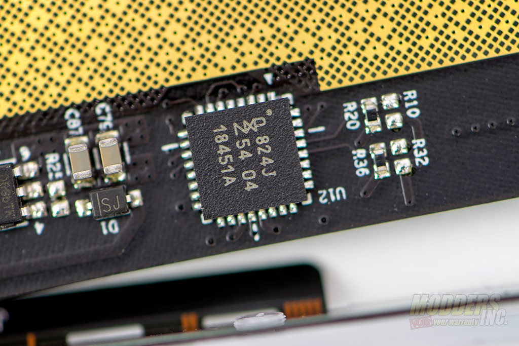
The NXP 824J is a micro controller from NXP that’s based on the ARM Cortex M0+. Since typically we don’t see many micro controllers on board memory modules, I’m assuming this is used to run the new Capellix LEDs.
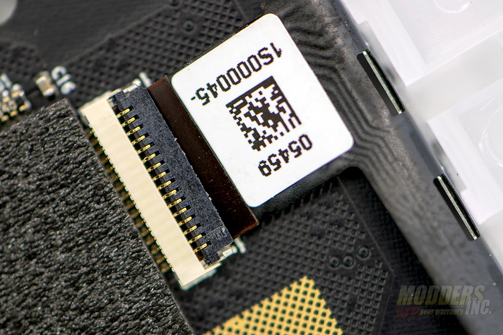
Speaking of LEDs, they are actually located on a thin metal strip that is attached to the diffuser at the top of the memory module. I tried to remove the strip to get a better peek at the LEDs however it proved to be a bit difficult and I really didn’t feel like ruining the LED capability on the modules. The strip can be completely removed from the modules however, by way of a small ribbon cable that plugs in on the non-memory side of the PCB.
