COOLER MASTER CM Storm Scout 2
Interior Impressions part 1:
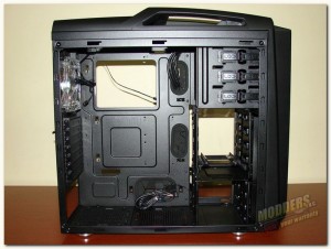
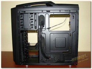
Side panel removal is pretty straight forward, just remove the thumb screws at the back of each panel and slide the panel backwards and off. Now we have or first look at the chassis of the Cooler Master CM Storm Scout 2.
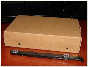
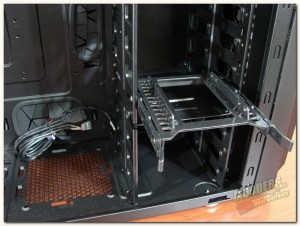
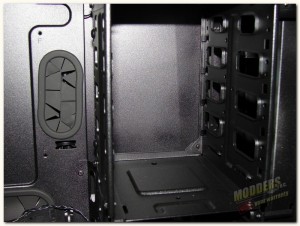
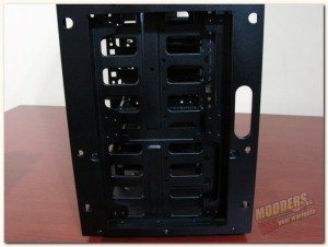
So, let’s start with the accessories, or should I say the accessory box. I really like how CM Storm place the accessory box in the chassis, it actually had HDD side rails attached to the box (via the small holes) and was placed inside the HDD cage. The box was wide enough with the rails attached to lock firmly in place inside the HDD cage.
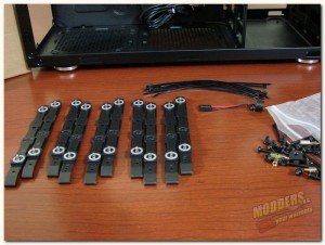
Inside the accessory box:
- 6 sets of HDD rails (counting the set of rails on the box and the rails on the 2.5″ HDD/SSD conversion tray)
- 10 wire ties for cable management
- 1 pc speaker
- motherboard standoffs (standoff socket tool included) + various other chassis screws etc
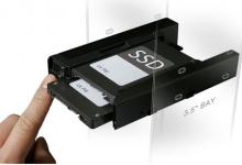
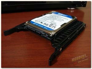
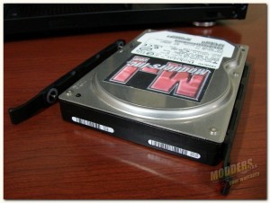
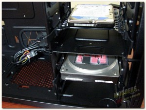
Mounted inside the HDD cage we find a 2.5″ HDD/SSD conversion tray. Using the side screw holes on the top of the tray you can mount a 2.5″ HDD/SSD on top of the tray in a 3.5″ HDD cage slot. However, CM Storm didn’t stop there, by utilizing the screw holes on the bottom of the tray you can mount a second 2.5″ HDD/SSD underneath the conversion tray. BTW, you can remove the side rails from the conversion tray and use another a 3.5″ HDD in the cage. Note: I did not have an available SSD at the time of the review, so I used a standard 2.5″ HDD for demonstration purposes.
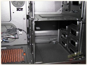
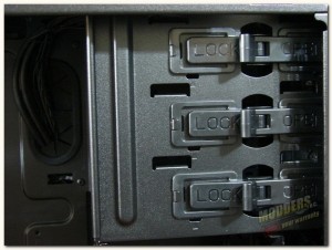
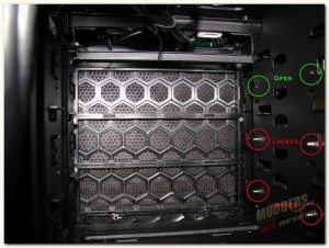
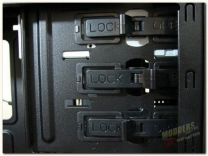
The optical drive bays utilize a tool-less locking mechanism to hold the optical drives in place. On the left you see the simple push to lock or open lever. On the right are the locking pins, from the inside of the optical bay. The red circles show the pins in the locked position, while the green circles show the pins in the open position.
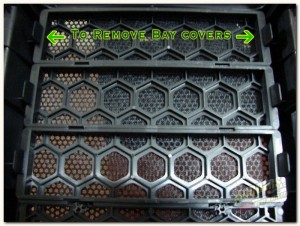
To remove the front panel optical drive covers you will have to remove the front panel from the case. To do this simply grasp the underside of the front panel firmly (there is an opening for your fingers there) and pull the bottom of the panel forward and off of the chassis. There are no wires connected to the front panel, so no need to worry about pulling a wire lose.
BTW, in the picture on the left with the front panel off, you can see where you can install either 2x 120mm fans or 1x 140mm fan for air intake.
Once you have the front panel off, simply turn it over and press the release clips, shown in the right picture above, and push the drive covers from the front of the panel past the clips and your now ready to put the front panel back on. Just hold the front panel up to the chassis and align the push pin type clips with the chassis holes and snap it back on. Your now ready to slide the optical drive through the front panel and into the chassis.
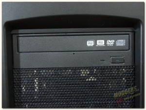
Slide the optical drive into the chassis until the front of the drive is even with the remaining drive cover. Once there simply switch the lever from open to lock and it should lock right in, however, if it doesn’t just slide the drive either back or forward a tad and the pins will snap into place. The optical locking mechanism does a very good job of holding the drive in place, as there wasn’t very much back and forth play or looseness in the drive.
