Biostar Z170X Gaming Commander Motherboard Review: A Measure of Control
A Closer Look at the Biostar Z170X Gaming Commander Motherboard
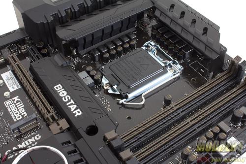
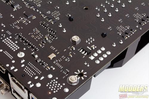
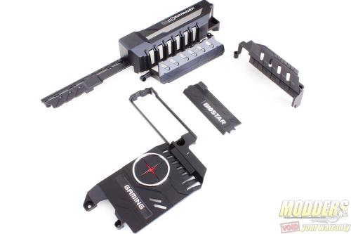
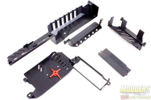
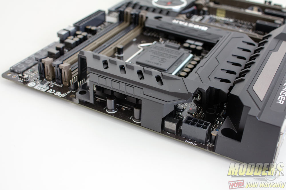
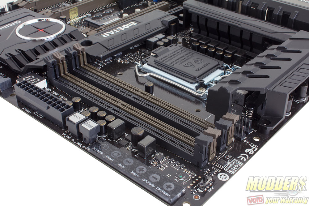
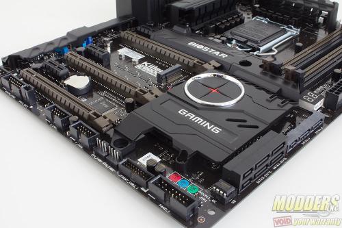
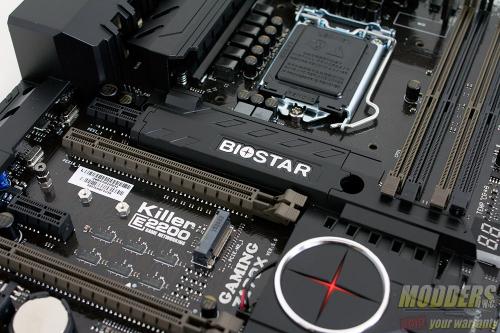
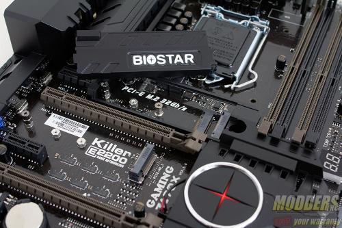
The Biostar Z170X Gaming Commander certainly looks a lot different compared to the Hi-Fi Z97WE and Hi-Fi Z97Z7 motherboards that I reviewed last year, not just because of the top covering but also the color matching Biostar has done. The Gaming Armor is secured to the motherboard with screws that use hex nuts at the back.
This mounting method is quite hardcore considering the Gaming Armor cover is very lightweight plastic. This however opens up lots of modding options including mounting metal accents. The VRM and chipset heatsinks underneath are painted black as well but I think having a contrasting paint color with the cover would make the Biostar Z170X Gaming Commander look even better. These covers also have airflow holes to account for thermal requirements so they have some functional aspect as well. The red star on the chipset cover is semi-transluscent and there is a slow-pulsing red LED behind it when the system is powered on.
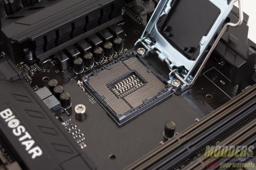
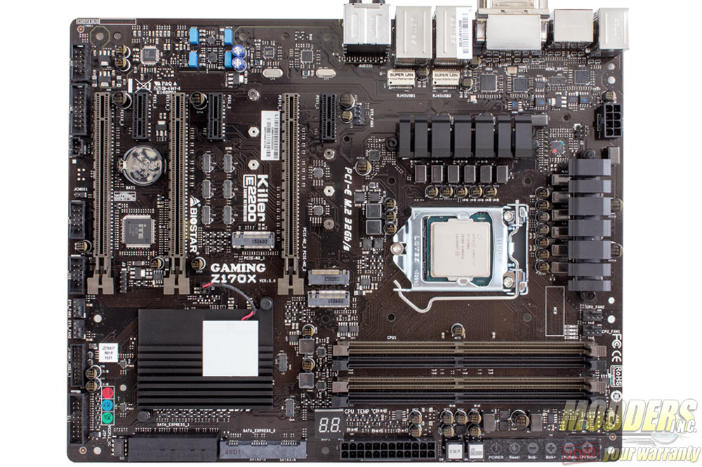
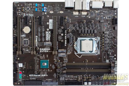
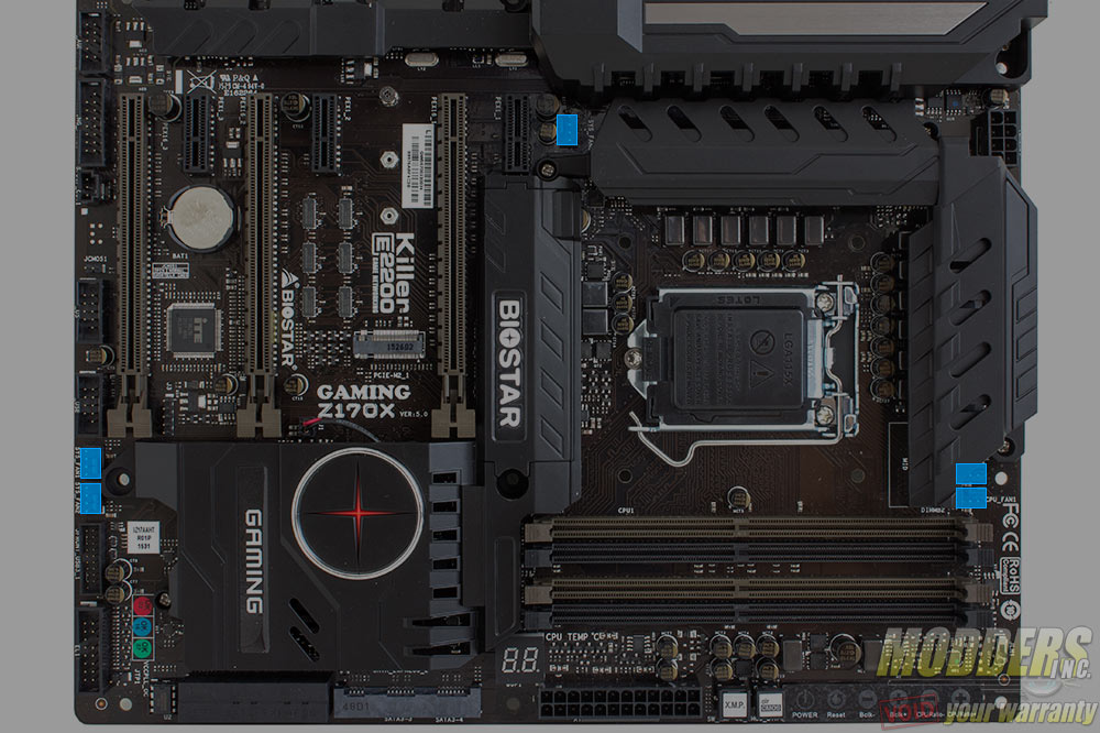
With the armor removed, the Z170X Gaming Commander does not look as intimidating anymore, although the military-looking brown color scheme still shows.
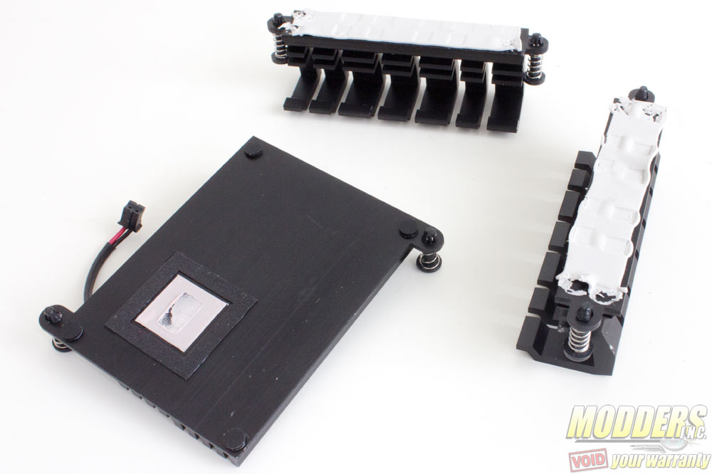
While the lightweight gaming armor using screws and hex nuts, Biostar for some reason uses push-pins for the VRM MOSFETs. The push-pins on the chipset is understandable as the Z170 chipset only has a 6W TDP but push-pins for the MOSFETs is not as secure as screws (can be tapped out of place with pressure from the sides). Plus, for a reviewer, they are a pain in the butt to remove.
The chipset heatsink uses the gummy pink thermal interface material which requires some rotating to dislodge instead of the usual grey goop or graphite sheet. The MOSFET heatsinks use a white thermal pad and the initial pressure is quite good, imprinting the MOSFET markings since the springs apply strong enough pressure from the top-down (just not from the sides).
The 8-pin EPS12V CPU power connector is at the top right corner, tightly squeezed right above but Biostar made the mistake of making it even harder for users to plug-in/unplug the cable by placing the locking latch at the bottom instead of the top. Users would large thumbs will have a hard time getting their finger in there with the Gaming Armor in the way.
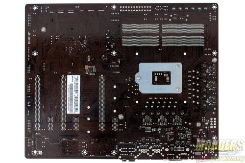
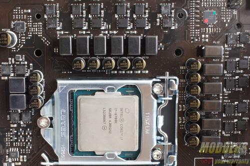
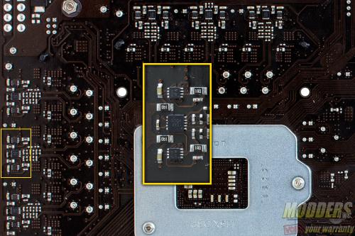
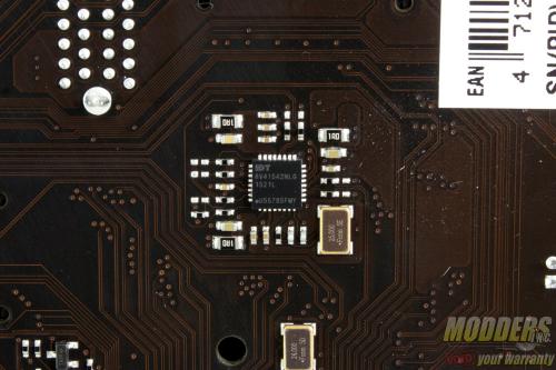
This is a bit different since this sample board has a sample IC for the main PWM (labeled ISL691XX). Intersil currently does not list any IMVP8 controller with a matching TQFN48 package but it is most likely a 4-phase controller, although the secondary controller for the IO and System Agent is clearly identifiable as an Intersil ISL95857 which is a 1+2+1 voltage regulator. An Intersil ISL6617AFRZ doubler is used per phase and are located at the back of the motherboard with the drivers (except for the System Agent at the bottom). Each phase uses Sinopower SM4377NSKP and SM4364NAKP Power-DFN SO8 package MOSFETs, similar to the Biostar Z97Z7 motherboard. An IDT6V41542NLG secondary clock is located in the rear as well for greater BCLK margins when overclocking. All the capacitors used on the motherboard are AP-Con 5K capacitors.
Four DIMM slots support up to 64GB of DDR4 at 4133MHz (4000MHz ratio + QCLK odd ratio for 4133MHz in the UEFI). A UPI Semiconductor uP1514R buck controller serves as the DRAM voltage regulator with a pair of Sinopower SM4377NSKP MOSFETs. On the top corner is an LN2 switch for booting under -130C temperatures (obviously it is turned off by default). The top right edge also contains Biostar’s new touch OC and onboard buttons. The Touch OC allows the user to overclock directly from the desktop when the TouchOC application is running, allowing for CPU ratio and BCLK adjustment. The power and reset buttons are also part of the Touch OC interface but the Clear CMOS and XMP toggle button are more tactile button options right above the 24-pin CPU power. The port 80 Debug LED which doubles as a CPU temperature is also located towards the bottom of the DIMM slot.
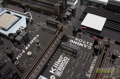
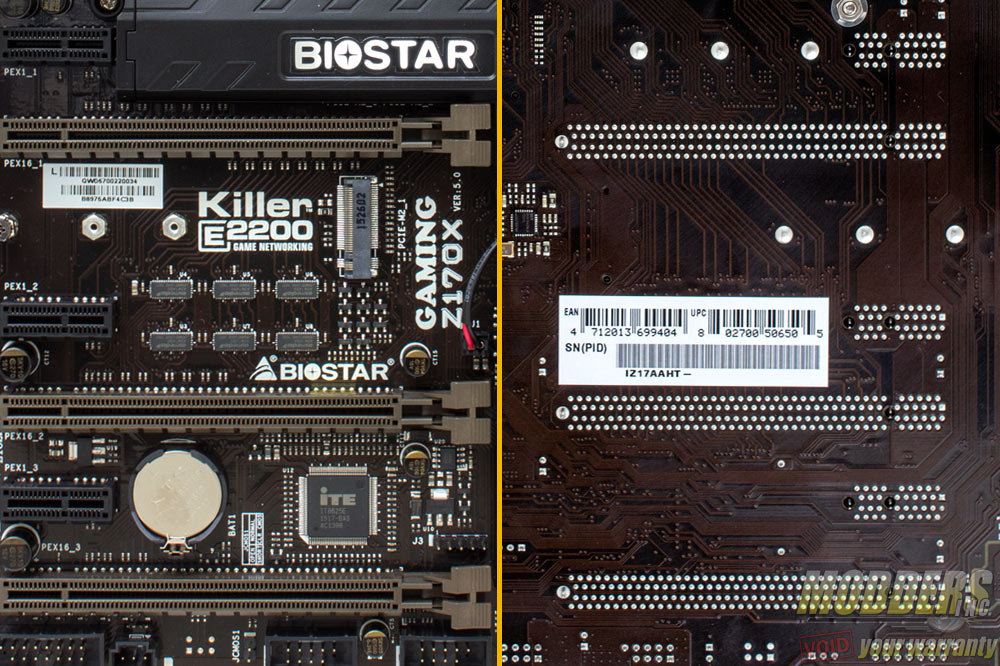
All storage options except for the rear USB 3.1 are provided natively by the Intel Z170 chipset. There are six SATA 6GB ports which also can function as three SATA Express ports. There are three M.2 slots, two of which are hidden with a cover at the center of the Gaming Armor cover. The Key-A slot can be used for Wi-Fi modules while the other M.2 slot can be used for storage including SATA or PCI-E x4 SSDs. ASMedia 1480 switches are used to share bandwidth between SATA Express function and M.2 storage function (only one can be used instead of the other at the same time).
Along the bottom right corner is the front panel header and the 19-pin USB 3.0 header. Two 9-pin USB 2.0 headers continue at the bottom as well as the SPDIF out and Gaming Panel header and front audio header. An ITE8628E SuperIO is in charge of hardware monitoring, PS/2 and Port 80 debug LED function as well as five PWM fan headers. There is no redundant BIOS options but the Z170X can recover from bad settings by itself (safe settings will reload if it fails to boot the first time with the settings implemented if it is not grave enough). Also, the Winbond 25Q64FVA1G located directly below the SATA ports is socketed and can be physically replaced when corrupted.
Expansion slot distribution is as follows (in order top to bottom):
- PCI-E 3.0 x1 via Z170
- PCI-E 3.0 x16 via CPU (x16, x8 when slot 4 is populated, switched by ASM1480)
- PCI-E 3.0 x1 via Z170
- PCI-E 3.0 x16 via CPU (x8, x4 when slot 6 is populated, switched by ASM1480)
- PCI-E 3.0 x1 via Z170
- PCI-E 3.0 x16 via CPU (x4)
Unlike some motherboards, Biostar opted for the third PCI-E x16 slot to be CPU wired instead and Tri-Crossfire is possible.
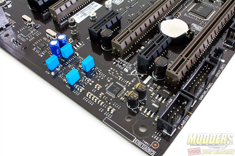
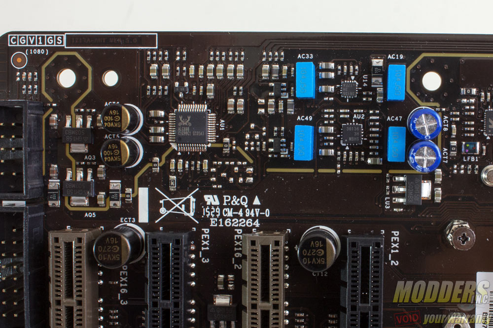
The audio subsystem is physically isolated from the rest of the PCB to minimize interference and audio is handled by a Realtek ALC898 HD audio codec, a superior solution to the ALC892 used in previous Biostar Z97 mainboards and as I mentioned in those review, better than the Realtek ALC1150 used by most motherboards in terms of better SNR for multi-channel because only the front DAC of the ALC1150 has a 110dB SNR while the rest are 96dB. The ALC1150 has better recording capability however but most gamers would not need that. Biostar uses some film capacitors and electrolytic audio capacitors here and has two chips for the pre-amp and the gain control with the SmartEar 3D application (I am unfortunately unable to identify these chips at this time).
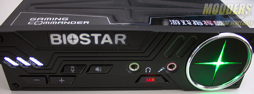
The Gaming Commander plugs in using one USB 2.0 header, the dedicated Gaming Commander header and HD audio header pass-through. The “mix” button toggles between the onboard Realtek based audio solution and the Gaming Commander’s built in audio controller. Volume control buttons as well as device mute buttons are also present.
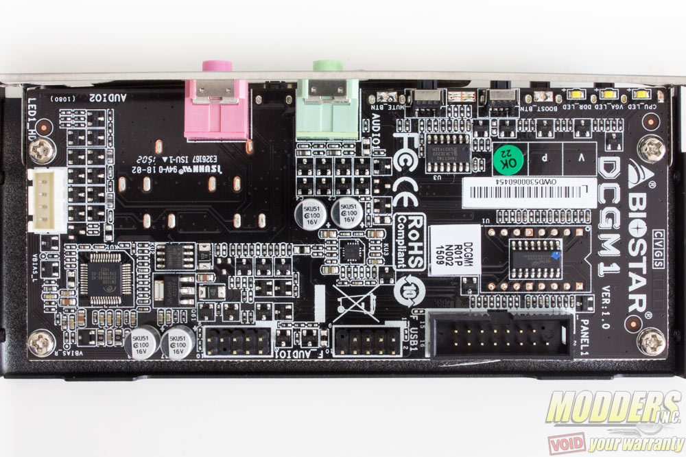
Opening the Gaming Commander reveals a C-Media CM120 based solution. Windows detects that this is a 2.1 audio solution and has 16-bit 44kHz and 16-bit 48kHz output settings. The Gaming Commander also serves as a quick debug LED showing activity of the CPU, VGA and memory and the Biostar logo alternating in color to indicated CPU temperature level: Green means that all is safe up to 70C, while yellow covers the 71C to 89C range and red means temperature has reached 90C or higher.
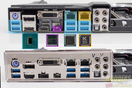
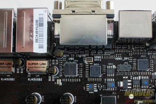
The rear PS2 port is provided by an ITE8628E Super IO chip. There is a DisplayPort (Maximum resolution supported is 4096×2160@24Hz or 3840×2160@60Hz) and two HDMI 2.0 ports available for integrated graphics users using a pair of Megachips MCDP2800BB. There is a DVI-D connector as well with an ASMedia ASM1445 HDMI/DVI switch (can only be used if the HDMI port below it is not in use).
There are five gold-plated configurable analog audio jacks with one optical audio out. Six USB 3.0 ports are available and Biostar uses ASMedia ASM1464 signal repeaters to optimize signal. A single USB 3.1 Type-C port is provided via an ASMedia 1142 host controller, bridging a PCI-E x1 lane to a USB 3.1 Type-C port. This is the future of connectivity and it is nice to see that the the Biostar Z170X Gaming Commander is ready for it. It is pretty much essential at this point going forward even though there are not many devices yet that can fully saturate it yet.
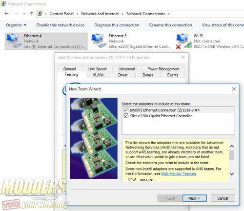
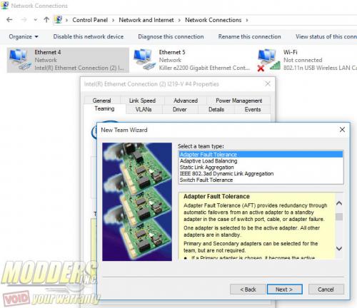
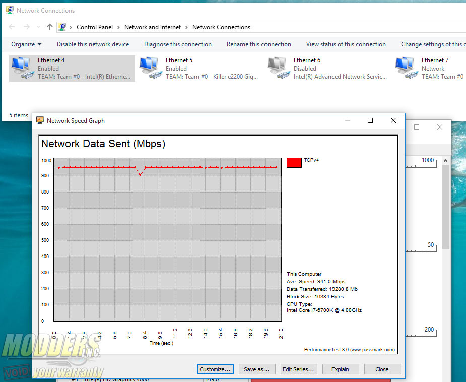
There are two Gigabit Ethernet NICs included on the Biostar Z170X Gaming Commander: one is Intel’s latest “Jacksonville” i219V while the other is Killer’s E2201 Ethernet solution. While this is not the latest solution from Killer, it is however capable of teaming with the i219V PHY.
