Biostar Hi-Fi Z97WE Motherboard Review
A Closer Look at the Biostar Hi-Fi Z97WE Motherboard
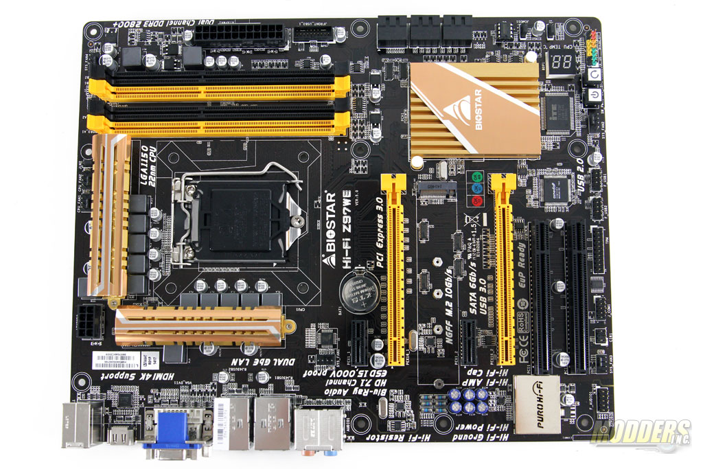
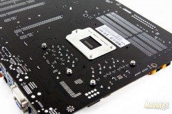
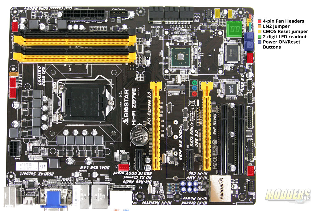
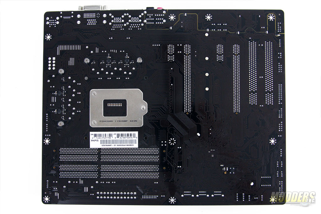
The Biostar Z97WE uses a standard ATX form factor measuring 305mm x 244mm on a 4-layer black PCB with visible brown surface traces. Like the Z77 Hi-Fi series, the color theme is a departure from Biostar’s traditional red color theme, now utilizing gold and yellow color combinations compared to the blue colored Z77 Biostar Hi-Fi motherboards.
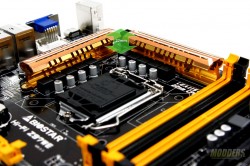
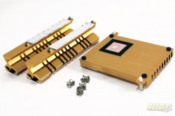
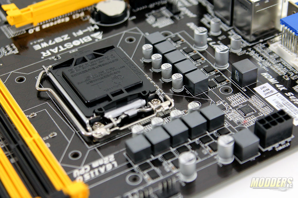
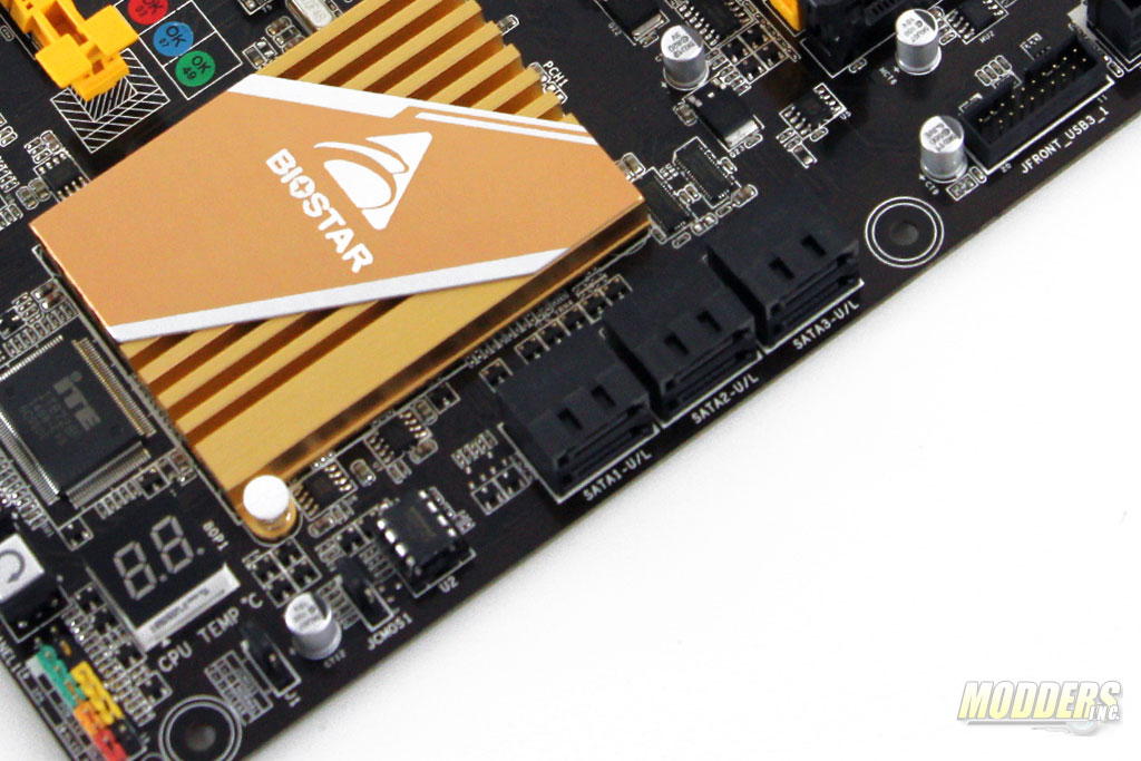
The VRM heatsinks are held in place by spring-loaded screws and design-wise, they are similar to the Z77 heatsinks, except golden in color. The Intel chipset heatsink is held in place by spring-loaded pushpins. The VRM heatsink is actually a two-piece design so modders can remove the top accent and paint it independently of the gold heatsink for a nice contrasting color.
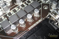
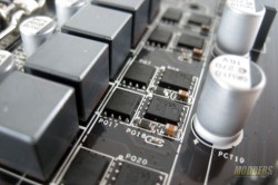
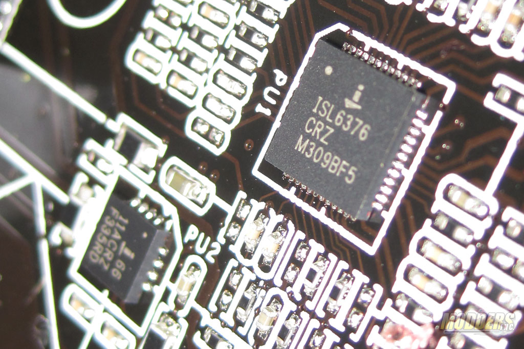
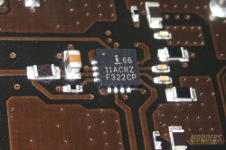
CPU Power delivery system consists of an Intersil ISL6376 VRD12.5 Hybrid PWM regulator that can control up to 6-phases, 5x pairs of Sinopower SM4377NSKP and SM4364NAKP Power-DFN SO8 package MOSFETs with 10x 0.50uH ferrite chokes and 8x 5K rated 560uF Solid AP-Con capacitors. The 10-phase design is realized with the use of Intersil 6611 driver/doublers, four in the backside and one on the top side (5 true phases doubled).
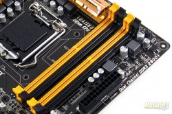
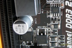
The memory power is controlled by a single phase uPI Semiconductor 1514r and uses two Niko Semiconductor P0903DBL TO-252 (D-PAK) packages, and a 1.2uF ferrite inductor. Maximum memory support is 32GB DDR3 across four DIMMs up to 2800MHz (divider OC).
Overview of some of the features on the Biostar Hi-Fi Z97WE:
RED – Fan Header Locations– There are six fan headers in total, all are 4-pin PWM which is great for a motherboard in this price range. In terms of layout, it would be preferable if the fan header at the bottom was placed closer to the front for practical reasons since most tower cases do not have fans on that area. CPU and CPU_OPT fan headers can be independently controlled. The sixth fan header for the rear exhaust is controlled by a Fintek F75308 since the ITE8728F SuperIO can only control up to five fan headers.
ORANGE – LN2 Jumper – The LN2 jumper enables the system to ignore the low temperature warning and boot at extremely low liquid nitrogen-cooled temperatures.
YELLOW – CMOS Reset jumpers –In case of OC failure, CMOS settings can be reset via jumpers located at the bottom right corner. There are two jumpers and resetting is a two-stage process, requiring users to move the top jumper first, wait 5 seconds then move the bottom jumper to reset.
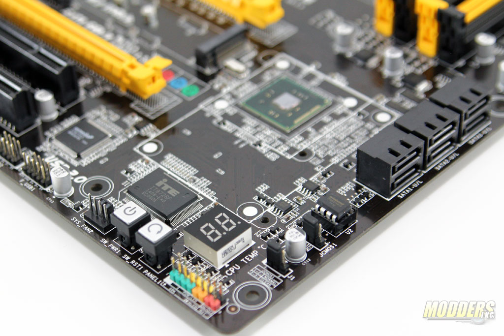
GREEN – LED Readout– A two-digit LED displays post code errors and status during boot-up and also doubles as a CPU temperature display with a one-second refresh update.
BLUE – Onboard Buttons– Onboard Power-on and Reset buttons allow for direct access when the motherboard is on a test bench without plugging in the fan headers to a switch.
The USB 3.0 header and six SATA3 ports are natively provided by the Intel chipset and are located at the right side middle edge. The SATA3 ports are angled to prevent clearance issues with long graphic cards.
Below the SATA3 ports is a socketed Winbond W25Q64FV 64M-bit serial flash and the CMOS reset jumper. The front panel headers are color coded for convenient installation and the polarities are printed onboard. Beside the two-digit LED and above the on-board buttons is an ITE8728F SuperIO responsible for providing the PS/2 connector in the rear, provides bus for the COM port and has the ability to control up to five PWM fan headers.
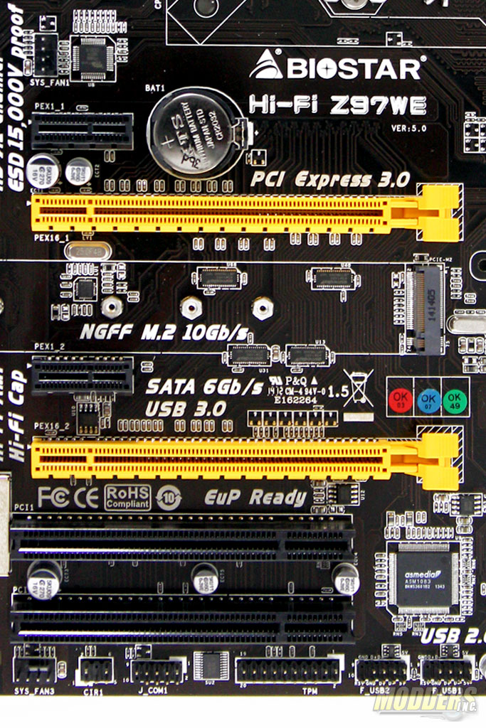
Further along the bottom edge, there are two 9-pin USB 2.0 headers, a Trusted Platform Module v1.2 header, an Advanced Analog Circuits 232GG chip bridging the ITE8728F for the COM port header beside it, and a consumer IR header for the Biostar BIO Remote functionality.
Expansion slot distribution is as follows (in order from top to bottom):
- PCI-E 2.0 x1
- PCI-E 3.0 x16 (16x when using a single video card and 8x when the second PCI-E 3.0 x16 slot is populated)
- PCI-E 2.0 x1
- PCI-E 3.0 x16 (Fully wired at 16x, runs at 8x when the first PCI-E 3.0 x16 slot is populated)
- PCI slot
- PCI slot
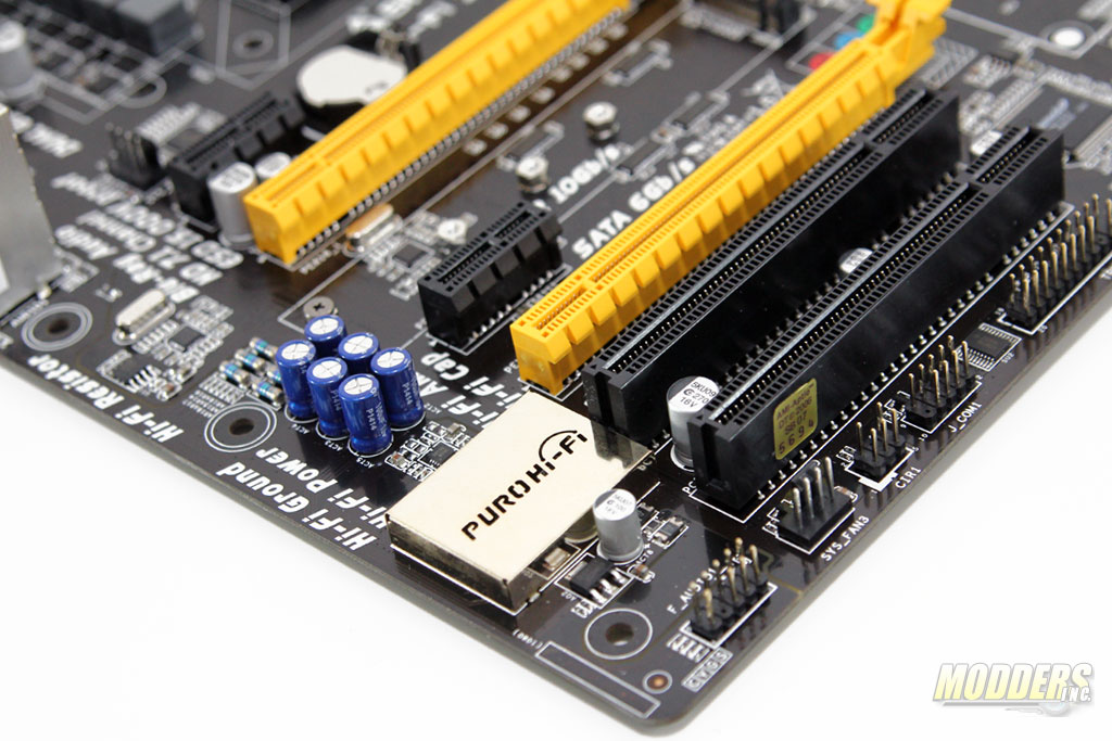
Switching duties between the two PCI-E 3.0 slots are handled by ASMedia 1480 switches while an ASMedia 1083 bridge takes up one available PCI-E 2.0 x1 from the chipset and provides two legacy PCI slots. An M.2 SSD can be installed in between the two PCI-E 3.0 x16 slots and shares bandwidth with the two topmost SATA3 ports when populated. There is a healthy gap between the two PCI-E 3.0 x16 slots for dual-Crossfire setups although if installing an M.2 SSD, the graphics card at the top-most PCI-E 3.0 x16 slot must be removed first.
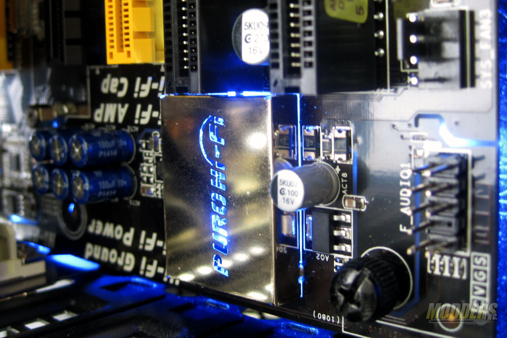
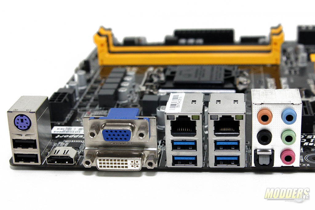
As with most mainstream and high-end Z97 motherboards these days, the audio sub-system is physically isolated from the rest of the system and the Realtek ALC892 codec is housed to minimize electro-magnetic interference. Biostar’s implementation is dubbed the “Puro Hi-Fi” and the dividing line lights up a blue LED when the system is powered on. Biostar uses several 75ohm metal-oxide resistors with 100uF 10V non-polarised audio capacitors. They look like ELNA RBP2s or ERSE’s on first glance but there are no brand markings on the sleeves and it looks like it was re-sleeved with the Biostar Hi-Fi mark on it. Pricing and the fact that it isn’t advertised suggests it is probably generic. There is also a headphone amplifier but I cannot identify the markings. Audio outputs in the rear include a microphone (pink), line-in (blue), front (green), rear (black), sub (orange) and optical out.
Unique for a motherboard in this price range is the presence of two Gigabit LAN ports via a pair of Realtek RTL8111G Ethernet controllers. The four remaining USB 3.0 headers available via the Intel chipset is available in the rear as well underneath the pair of Ethernet ports. Video output for the Intel HD graphics include a VGA and DVI-D for up to 1920×1200 @ 60Hz and an HDMI port that can handle resolutions up to 4096×2160 @ 24Hz.


Great review as usual, i might suggest to you guys to add a article navigation bar like other sites do, sometimes we want to find a specific topic like overclocking, power consumption, specs tec.
Thanx
Working on trying to find the right plug-in that will do that.
Thanks for the suggestion. We could probably do a temporary solution for now with manually created table of contents linking to each page. I will update the previous articles.