ASRock B550 Extreme4 Motherboard Review
A Closer Look at the ASRock B550 Extreme4
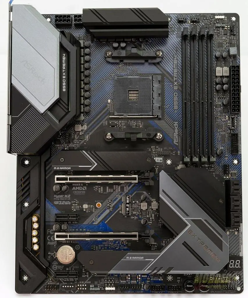
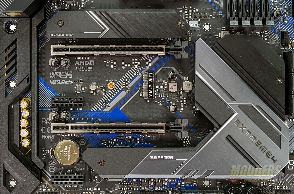
The ASRock B550 Extreme4 has a sudo-futuristic look to it with the harsh and sharp angles of the heatsinks on the CPU power delivery and the B550 chipset. The heatsinks use a black/grey color scheme that is offset by the black/blue color theme of the PCB. The motherboard houses two full-length PCIe slots although only the top is electrically configured to run an x16 and two PCIe 1x slots. The B550 Extreme4 also houses two M.2 slots on the motherboard. Thankfully unlike the X570 Taichi that I have only one of the M.2 slots is tied into the B550 chipset heatsink. Also, take note that there is an M.2 Wifi module header located between the two full-length PCIe slots.
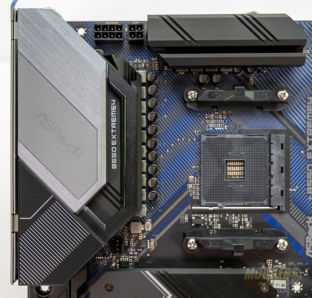
Starting at the top left of the motherboard when you’re looking at the CPU socket, you’ll find the CPU power connector. ASRock has configured an 8+4 connector here to help deliver more power to the CPU during high frequency overclocking. During my testing, I only used the 8-pin power connector and did not experience any issues. Following the board edge around to the right, you’ll find the smaller of the two CPU VRM heatsinks. The heatsinks are made from aluminum and are bolted through the board and use a thermal pad to ensure full contact with the MOSFETs below.
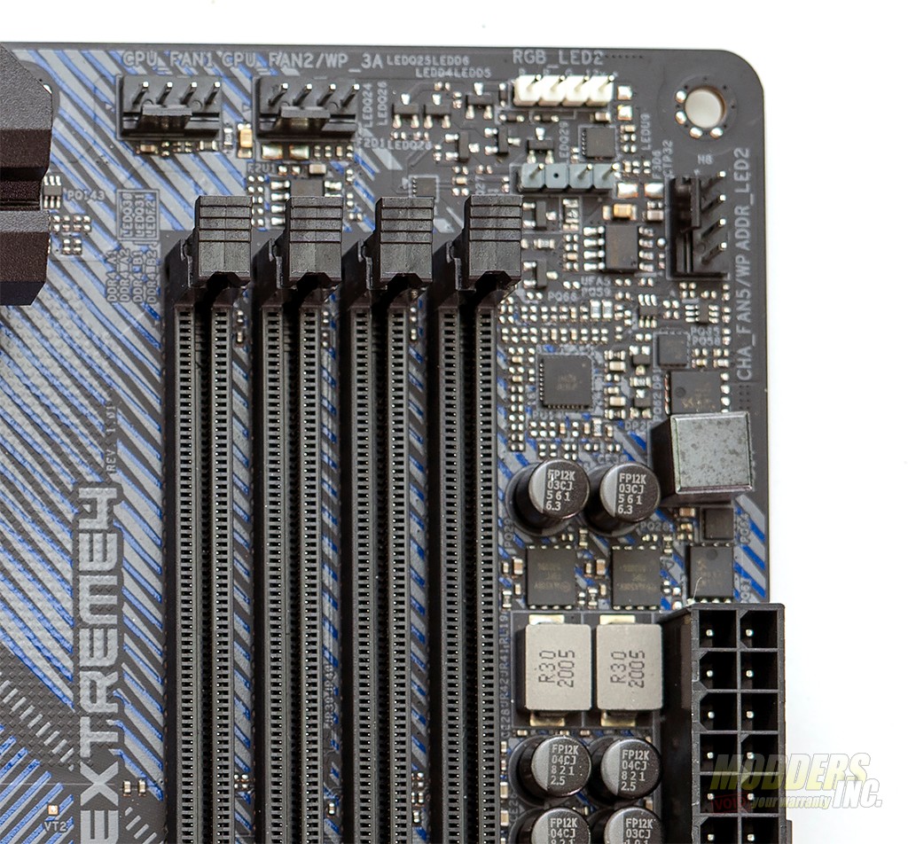
Just above the memory slots on the B550 Extreme, you’ll find two fan headers label CPU_FAN1 and CPU_FAN2/WP. Both headers are PWM and can support a variety of PWM fans and pumps on the market. There are also two RBG headers just to the right of the fan headers. One is for a standard 12v 4-pin RGB connector the other is the 5v 3-pin addressable RGB (aRGB) connector and are tied into ASRock Polychrome Sync RGB lighting system. An additional PWM fan header sits just above the 24-pin motherboard connector and is labeled as FAN5.
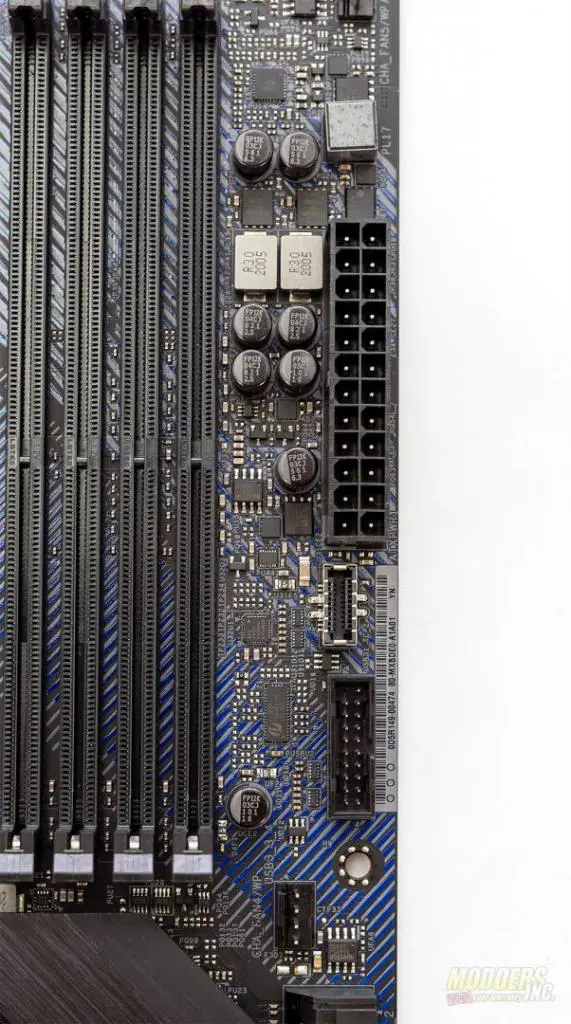
The right edge of the B550 Extreme4 houses the 24-pin motherboard connector as well as a USB C front panel I/O connector and a front-panel USB 3.0 connector just below the 24-pin connector. An additional PWM fan header is provided and is labeled as CHA_FAN4.
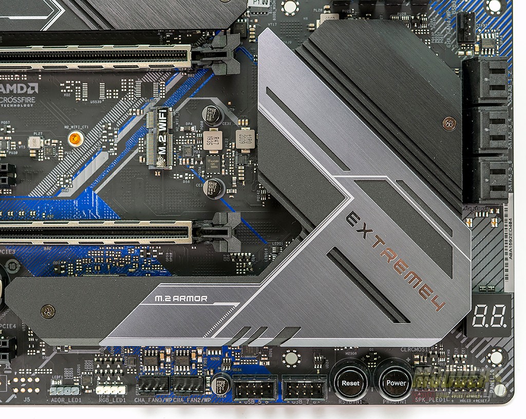
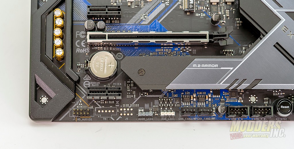
Moving to the bottom right of the motherboard, you’ll find 6 SATA 3.0 ports. Below is the diagnostic LED panel. This panel will give you a code that you can reference in the manual if you have issues with the motherboard. Moving along the bottom edge of the motherboard from right to left, you’ll find the front panel power, reset, and LED connector. Next, there is the onboard power and reset button. This is a handy feature to have when testing and burning in a motherboard and I wish that all motherboards came with them. next up and the front panel USB 2.0 headers that support two USB 2.0 ports each. Fans 2 and 3 and the next 4-pin fan headers that you’ll come across. Two more RGB headers are provided next and just like above, one is for 12v 4-pin RGB and the other is for 5v 3-pin aRGB.
Rounding out the bottom edge of the B550 Extreme 4 is the front panel HD audio connector. The audio circuitry is located on the lower left side of the motherboard and is covered by the left side heatsink. Only the audio capacitors are left exposed.
As I mentioned earlier, there are two full-length PCI express slots on the B550 Extreme4. If you look carefully, you’ll see that only the top slot has connections that run the full length of the slot. This is the X16 slot. The other slot is electrically configured as X4. Depending on the CPU used, the top slot is capable of either PCIe Gen 3 x16 OR PCIe Gen4 x16. The second slot as well as the PCIe slots only run at PCIe Gen3 no matter the CPU. The top M.2 slot is the PCIe Gen 4.0 capable (again, CPU dependent) M.2 slot whereas the bottom is only capable of PCIe gen 3.0 however both are x4 slots. The M.2 Socket in the center of the PCIe slots is a Key E type and supports type 2230 WiFi/BT modules. To be honest, I was a little taken back that this motherboard didn’t include WiFi. It is the first that I’ve reviewed in a while that didn’t.
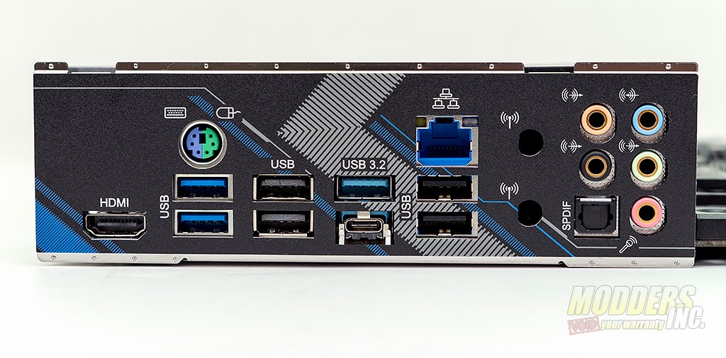
The rear I/O shield features an HDMI connector for the AMD Ryzen APUs that have an onboard GPU. Next up is a combo PS/2 port and two USB 3.0 ports. The next USB ports are 2.0 capable. The 3rd set of USB ports provided are USB 3.2. One is a type A connector that we’re all familiar with. The lower connector is the newer type C connector. Not only does it allow faster speeds but it doesn’t matter which way you plug it in. The USB 3.2 ports are followed by a 2.5 gigabit RJ45 LAN connector and two more USB 2.0 ports. ASRock has provided WiFi antenna mounting holes for those that choose to put an M.2 WiFi card on the board. Audio I/O is provided by 5 3.5mm jacks and 1 digital optical port.
