AORUS Z270X-Gaming 5 Motherboard Review
A Closer Look at the Gigabyte Z170X-Gaming 5 Motherboard
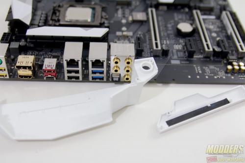
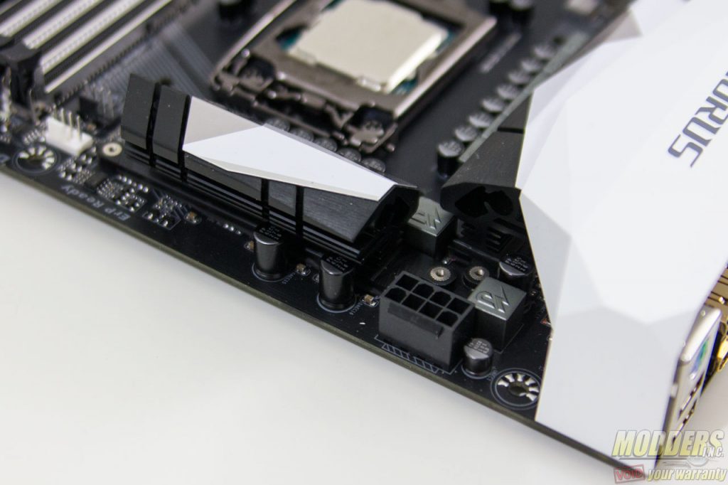
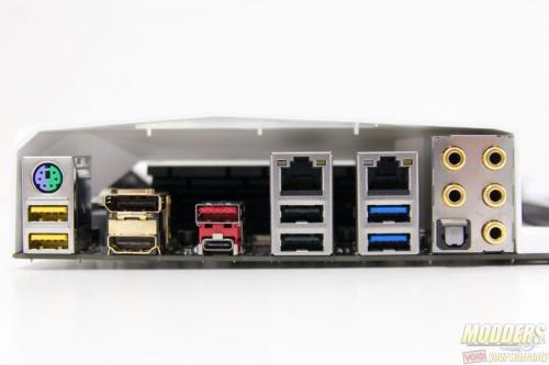
A white IO cover is pre-installed as a cosmetic feature, but this can be removed via screws in the rear.
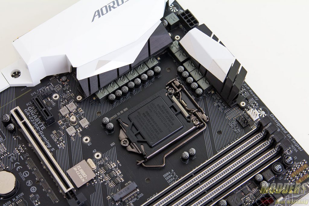
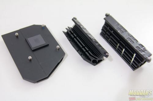
The VRM coolers are made up of two identical, non-heatpiped pieces weighing 64 grams and 51 grams. These are black anodized aluminum heatsinks with a white accent plus thin brushed metal sheet design glued on top so it is easily moddable. Aorus uses a thick gray thermal tape in between the MOSFETs and the heatsink.
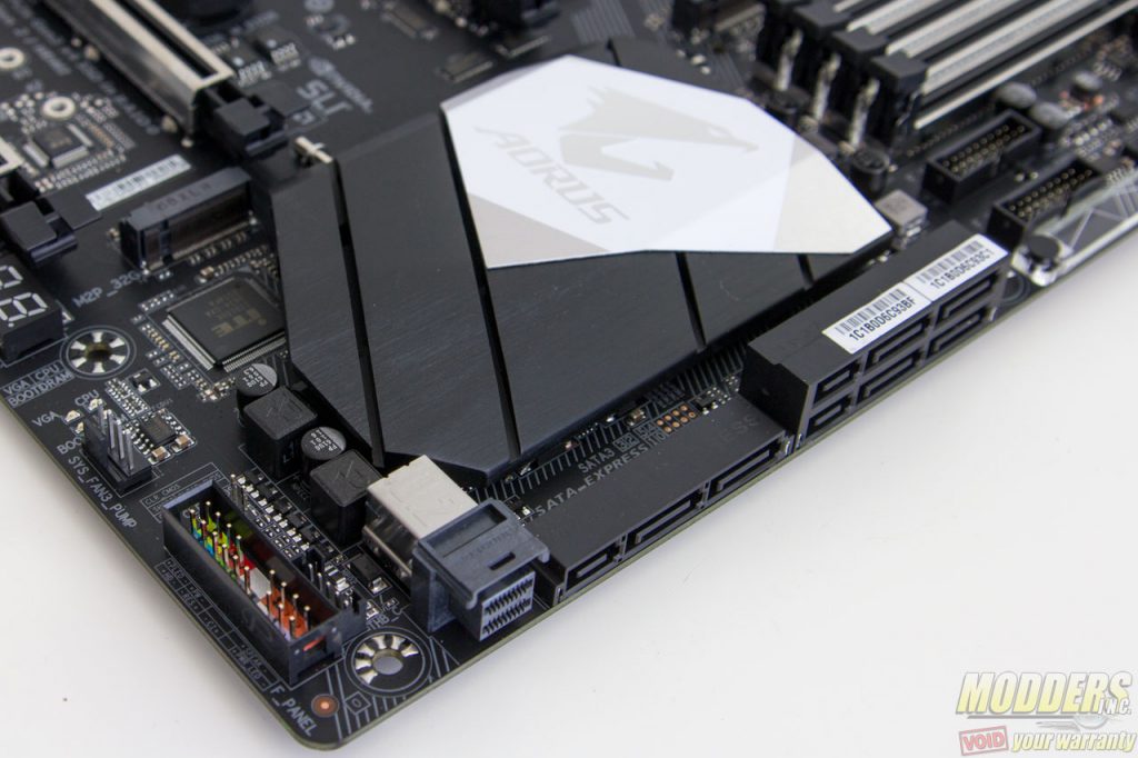
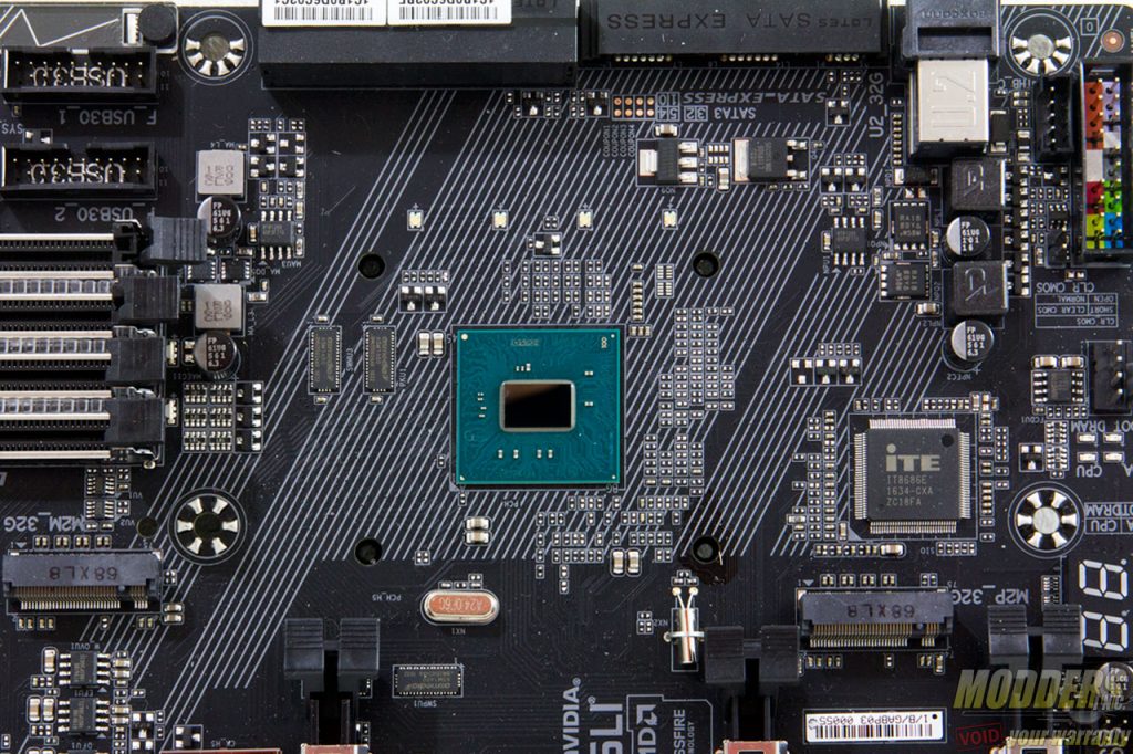
The chipset heatsink weighs 45 grams and the accent on it can be removed or modded in the same way as the VRM heatsink. A thin graphite thermal sheet is used as an intermediary between the chipset and this heatsink instead of a thicker thermal tape or thermal interface paste. The audio armor piece weighs 15 grams and does not act as a heatsink of any sort. It is purely cosmetic and easily moddable as well considering it mounts easily via screws from the rear.
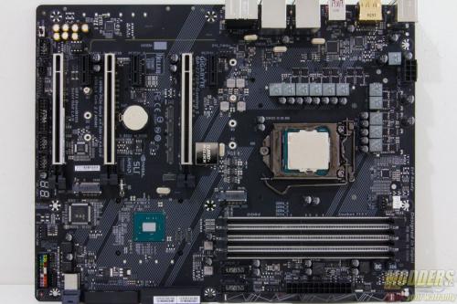
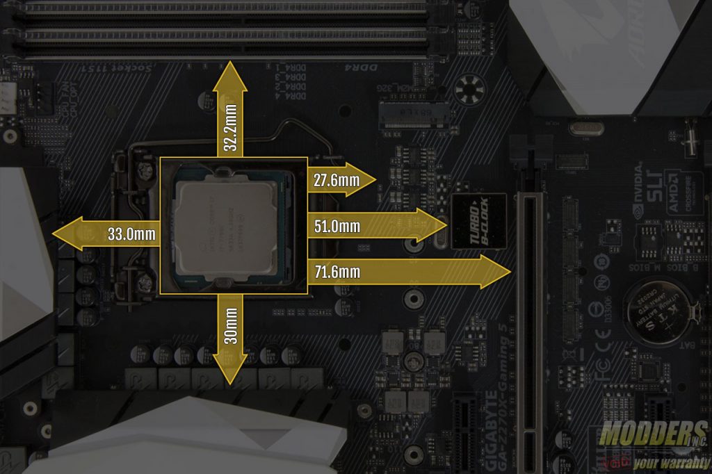
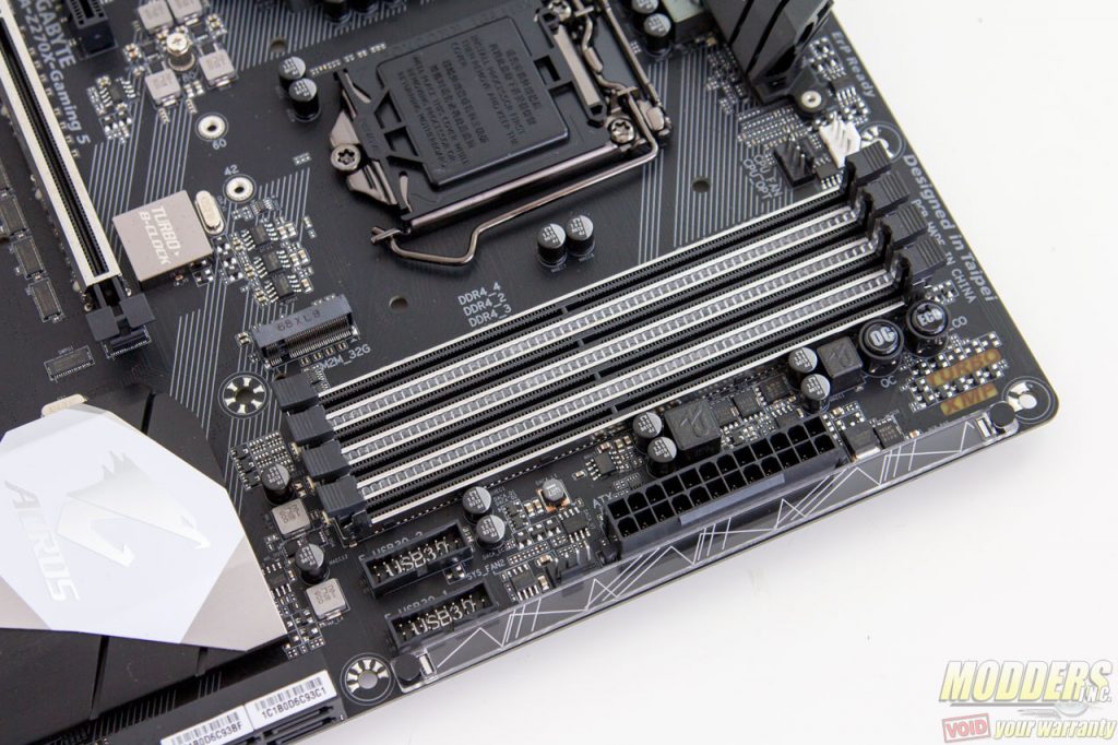
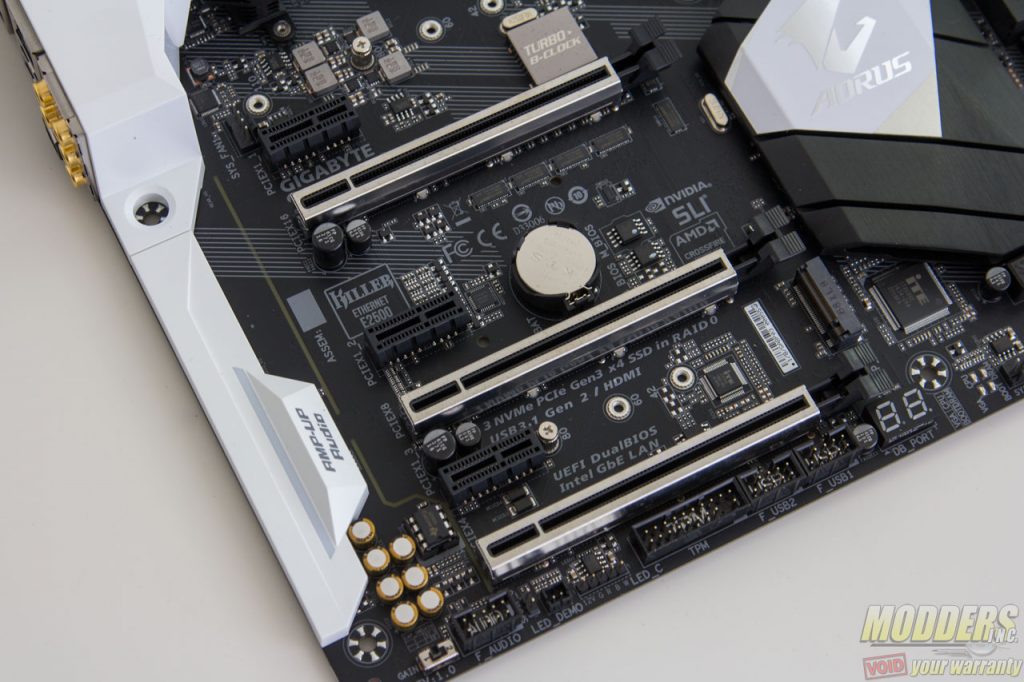
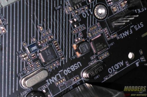
The space is very generous for the RAM clearance at 32.2mm compared to many motherboards that are 27mm or under. The layout is also quite similar to the Gigabyte Z170X-Ultra Gaming with the M.2 slot directly positioned right above the top-most PCI-E x1 slot and below the CPU socket where the bank of linear regulartors and MOSFETs for the minor CPU rails are. This M.2 slot supports up to 110mm long devices. Unlike the Z170X-Ultra Gaming motherboard however, the AORUS Z270X-Gaming 5 is equipped with the “Turbo B-clock” IC (it is hidden underneath a shiny metal housing), a secondary clock generator for refined BCLK overclocking.
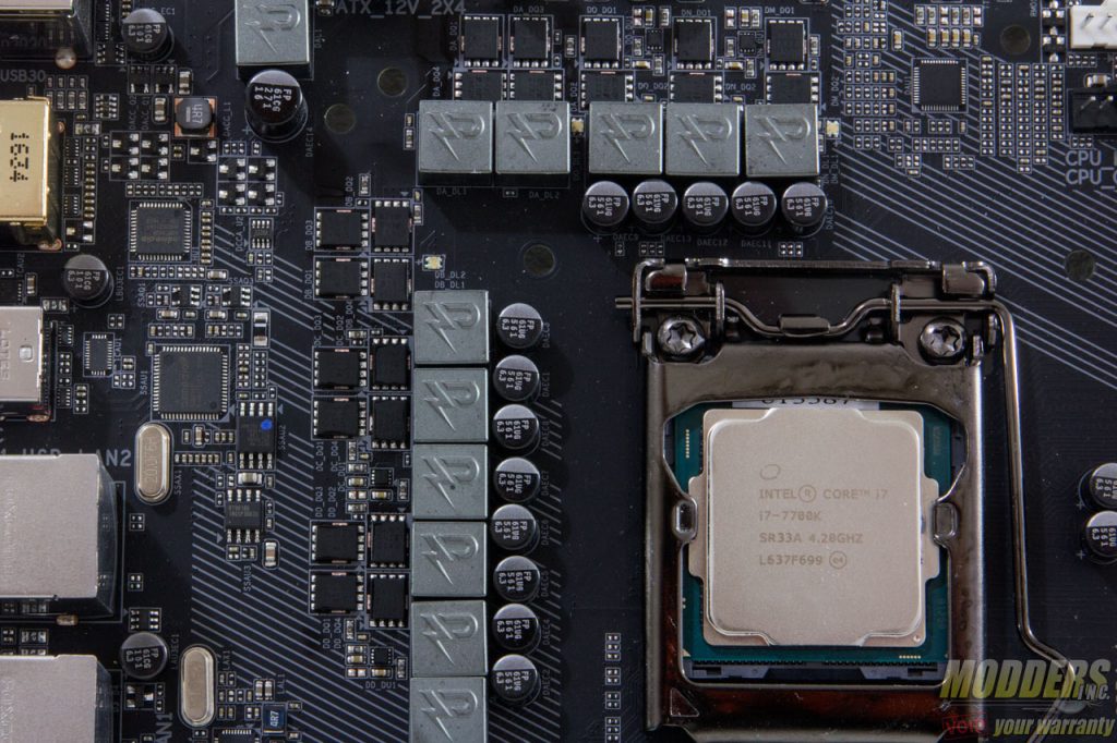
The main PWM controller is an Intersil ISL95866, a dual-output 4+3 phase capable IMVP8 controller from Intersil for the CPU+GT.There are three integrated drivers in total on this controller, two of which are on one output (voltage regulator A) while the third one is can be used on the voltage regulator that can be configured up to three phases. All of these drivers are used and additional Intersil ISL6625A drivers are utilized to drive Vishay SiRA18DP and SiRA12DP TrenchFET MOSFETs. Output filter has custom 500nH chokess with 561uF Japanese FP caps.
The 8-pin EPS12V CPU power connector is at the top right corner, tightly squeezed right above the VRM heatsink and beside two chokes. Gigabyte was wise to make the latch for this power connector facing upward so it is easier to release later during uninstallation. The 4-pin fan header for rear placed exhaust fans is positioned further down closer to the bottom edge of the rear IO.
The DIMM slots have a metal “armor” around them and only lock on the top end part while the bottom part is fixed. A Richtek RT8120D is used for the memory VRM with three SiRA12DP FETs, a pair of 561uF FP caps and a 1KnH choke. Another 4-pin fan header is located here, right below the 24-pin connector. An OC switch an and ECO mode switch is located on the top right corner. These are for quick switching to preset configurations like in the UEFI EZ mode screen.
Onboard storage begins with a pair of 19-pin USB 3.0 header right below the 24-pin power supply connector. This is natively from the chipset. Also provided are six SATA3 headers, two pairs of are angled which can be used as SATA Express, although do not hold your breath for any SATA Express devices any time soon. What is exciting however is the inclusion of an embedded U.2 connector.
One m.2 slot is located right below the CPU socket which can also be used with an m.2 to U.2 Mini-SAS add-in card. It can be plugged into one of these m.2 slots and be able to run up to three NVMe SSDs in RAID 0 (M.2 or M.2 with U.2 converter + U.2 + PCI-E). This slot also supports 22110 form factor M.2 cards in length.
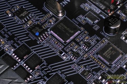
If a drive is installed on the bottom-most PCI-E slot, SATA ports 0 and 1 are disabled, using ASMedia ASM1480 switches to toggle. Even if it isn’t an SSD installed here, as long as this slot is populated, SATA ports 0 and 1 are disabled. You can see that Gigabyte has prioritized the storage plexing so that it has as little interference to the rest of the lane allocation besides the SATA ports.
Along the bottom right corner is the front panel header but this should be very easy to spot considering it is marked with the polarity and color coded. The G-connector accessory also makes installation easier. There is clear CMOS jumper header right above the front panel header bank. There is also a thunderbolt connector header available for a Thunderbolt add-in card. Another PCIe Gen3 x4 M.2 slot is located right between the second and third PCIe x16 slots. This one however is limited to 2280 form factors due to a PCIe x1 slot on the way.
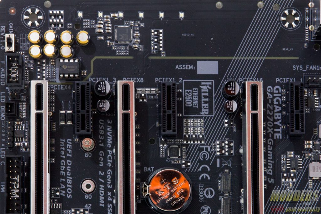
Expansion slot distribution is as follows (in order top to bottom):
- PCI-E 3.0 x1 via Z170
- PCI-E 3.0 x16 via CPU (x16, x8 when slot 4 is populated, switched by ASMedia ASM1480’s)
- PCI-E 3.0 x1 via Z170
- PCI-E 3.0 x16 via CPU (x8)
- PCI-E 3.0 x1 via Z170
- PCI-E 3.0 x16 via Z170 (x4, shares bandwidth with SATA 0, 1)
The Z270X-Gaming 5 motherboard’s PCI-E retention slots are reinforced with soldered-through shielding. This prevents the motherboard from getting damaged just in case something heavy drops on your video card that dislodges it.
The rest of the headers along the bottom include a pair of 9-pin USB 2.0 headers, a trusted platform module header, RGB LED header and front panel audio headers with SPDIF output. The RGB LED header is for connecting RGB LED strips which then can be controlled in sync with the Aorus Z270X-Gaming 5 either via the RGB LED options under the UEFI or the desktop software application.
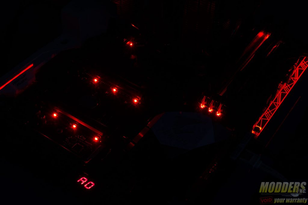
The audio subsystem is physically isolated from the rest of the PCB and audio is handled by a Realtek ALC1220 HD Audio codec capable of up to 32-bit playback unlike the popular Realtek ALC1150. This audio subsystem lights up with RGB LEDs (set to red by default) lined up at the rear of the PCB that shine through the isolation border. Nippon Chemicon audio capacitors are used for filtering in this area and a Texas Instruments NE5532P amp is used for the rear IO audio output which is socketed and can be replaced if wanted. There is also a gain adjustment switch right at the bottom for the front audio panel.
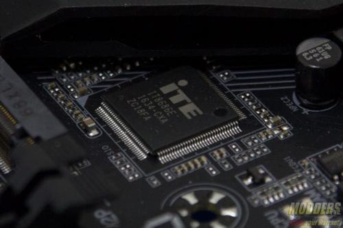
The rear PS2 port is provided by an ITE8686E Super IO chip which also handles system and temperature monitoring functions. There are two Gigabit Ethernet NICs included on the Aorus Z270X-Gaming 5, one is Intel’s latest “Jacksonville” i219-V PHY while the other is a Killer E2500.
There is a DisplayPort 1.2 (Maximum resolution supported is 4096×2304@60Hz and an HDMI 1.4 port supporting 4096 x 2160 @ 24Hz.
For rear audio, there are five configurable analog audio jacks with one optical audio out with all the analog jacks having gold plating. The yellow USB ports in the rear have the USB DAC-AMP function configuratble in the BIOS or via the Aorus DAC-AMP desktop software. Two USB 3.1 Gen 2 ports are provided, one Type-C and one Type-A via ASMedia ASM2142 controller.
