Alphacool Eisbaer 240 AIO CPU Cooler Review
Installation
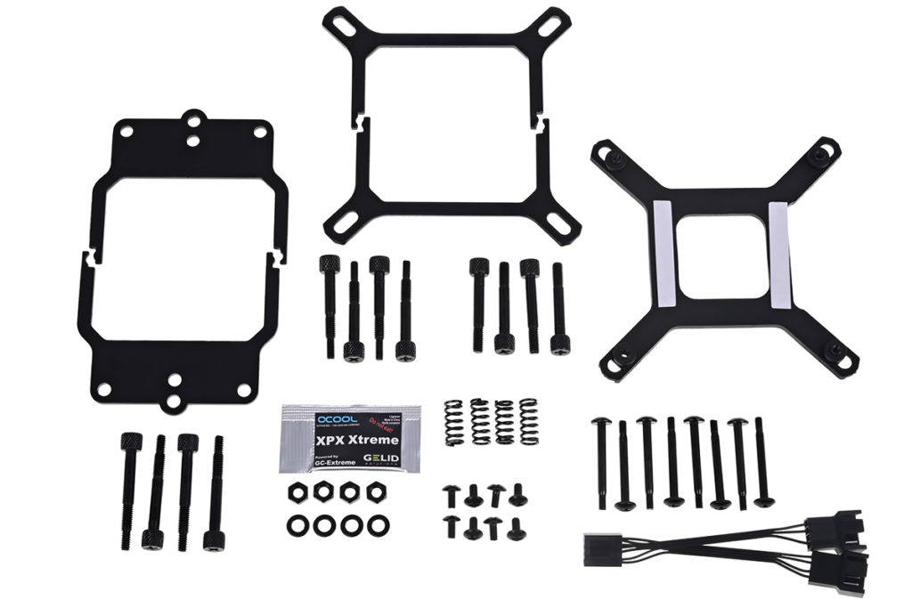
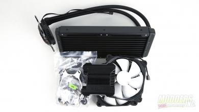
Before proceeding with installation, lay out all accessories and cross reference the package content with the illustrated user’s guide.
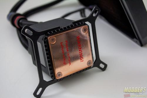
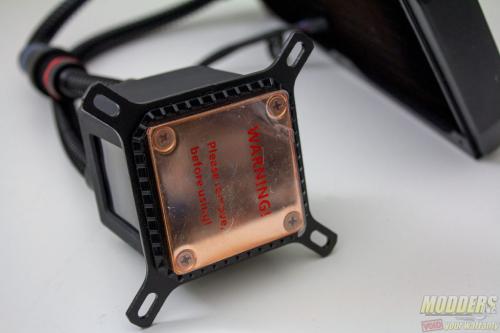
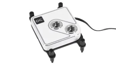
Intel users have to assemble the square mounting bracket on the base of the block, while AMD users have to install the rectangular bracket. It is basically a matter of snapping the two pieces into place as there is a groove around the bottom of the pump block already for them.
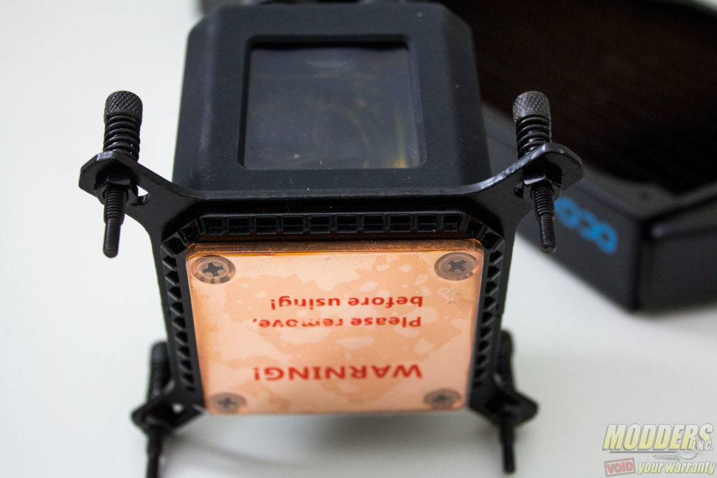
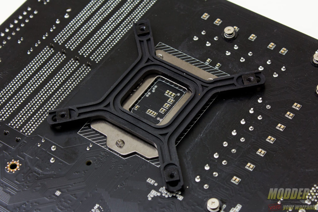
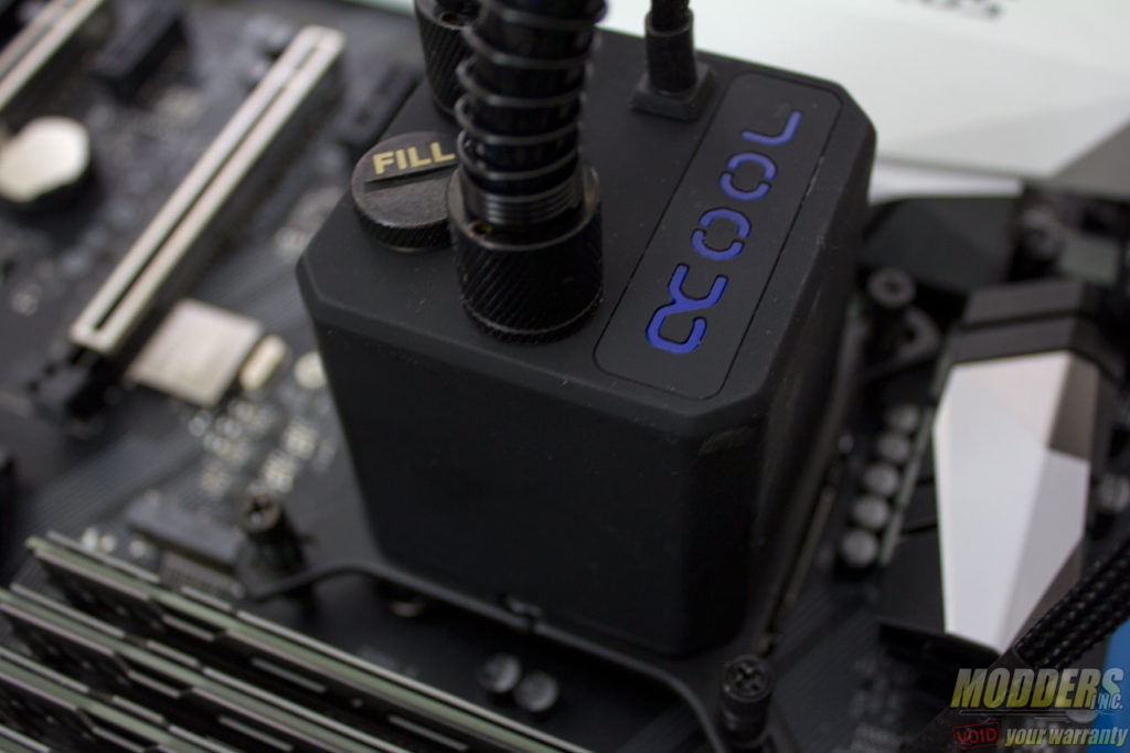
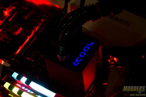
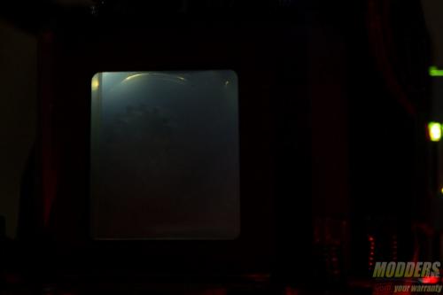
Plug in the pump connector to any available motherboard header. Some motherboards such as the Gigabyte AORUS Z270X-Gaming 5 have a dedicated header for a water-cooling pump for example. If working properly, it should light up a blue LED on the Alphacool logo when the system is powered on. There is also a little of light shining through the window on the pump block unit.
The radiator mounting is dependent on the case but it is fairly self-explanatory. The radiator can be mounted directly on a case as well using the shorter screws which require a screw driver to install.
Clearance Compatibility
The test motherboard is an AORUS Z270X Gaming 5 motherboard and measuring from the edge of the socket (the gray plastic part), there is a 32.2mm gap between the CPU socket and the first DIMM slot. The m.2 slot is 27.6mm away from the CPU socket, while the first PCIe x16 graphics card slot is 71.6mm away.
There were no clearance issues observed as the pump block unit falls well within the Intel keep out zone. The elevated copper contact also alleviates any possible issue or conflict with larger capacitors surrounding the CPU socket.
Both the PCI-E socket and the DIMM slots are also quite clear of any possible obstruction. There is still plenty of room here.
