12V Pump Switch
Introduction:
If you have a water cooled PC and are worried that one day you will neglect to turn on the pump and end up frying your hardware then this is a definite must read guide. Americanfreak has written a very easy to follow guide that shows how to insure your water cooled investment by taking the "what if…?" out of the equation.
After you take the plunge to water cool your computerthe next fear sets in… 'what if I forget to turn on the water pump'. I think we all know what the answer is to that question, so I set out on a quest to find the answer to my dilemma. Google here I come. I found a couple of places that were selling just what I wanted, but they where listed 'Out of Stock' and I wanted to do it right now!
By looking at the pictures I could get a pretty good idea on how they did it and having some knowledge of electrical controls it seemed to be pretty easy to do. The idea behind this is that when you push your on/off button it would start your computer and the water pump at the same time using 12volts DC supplied from the power supply. I finished a few rough layouts on paper and I was off to Radio Shack. After looking around the store for a while, I found all the stuff I needed.
Here is my list.
1-pkg Dual General-Purpose PC Boards #276-148A @ $1.69
1-pkg (of 4) PC Board Terminals #276-1388 @ $2.29
1-DPDT Miniature PC Relay w/12VDC Coil #275-249 @ $4.99
(You could use a SPST)
Total with tax $9.70
Not too bad of a hit in the wallet.

NEXT PAGE
Here is how I'm going to wire it all together. The drawings below show the coil without power to the coil and then with power to the coil.

You could use a SPST (single pole/single throw) Relay Coil. That would mean that you would have only one set of contacts. They would be Normally Open with no power to the 12-volt coil. I used a DPDT since that's all they had at Radio Shack.
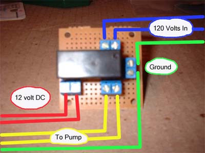
After getting home I did a couple of "dry" fits with all of the components to see which way would be the best. The picture below is what I came up with. This is how the wires will be attached to the completed switch/relay. The three wires from the 120 volt power (2 blues and a green in the picture) will connect to one side, the ground wire from both the power and the pump with be put together. The wires from the pump (2 yellow and 1 green in the picture) will connect to the other terminal. Finally the 12-volt power (2 red in the picture) is connected to the last terminal. Getting the 12-volt power to the relay will be up to you. I have a power bus inside my computer and decided to use that. You could get the power from a power connector or from a fan power supply on the motherboard itself. Just as long as when you turn on the computer it will supply the 12 volts to the coil.
NEXT PAGE
I used a power plug from an old AT power supply that didn�t work (I think we all have one of those) to bring the power inside the computer to the switch. This way I could use a regular computer power cord to power up the pump. I used the plug and made a pattern. Then I used that to cut my case. It was a small hole maybe 1 �� by �� at the bottom rear.
Now some people have been putting this whole setup inside the power supply and still using a second cord. Why? I�m not sure. If I were going to open my power supply I would get all the power from there.
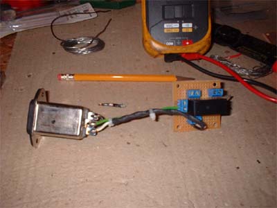
I used some silicone on the bottom of the PC board just to make sure that it could not short out. I also added screws to the PC Board for stand offs. Wanting to finish this off in a top-notch way I knew I needed a box to put my switch in. So I headed to Fry�s Electronics to see what they had. I found an aluminum box just slightly bigger than my switch. I decided to also add a green LED to indicate when the switch had power. This added about $3.00 to the total price of the project. I spent about $13.00 total.

NEXT PAGE
Here is the switch all done and installed. It worked like a champ the first time. You can buy different types and styles of pump switch and I highly recommend doing so if you do not want to try this on your own, but we all know that half the fun of Modding is doing it yourself.
Now the only problem is "what if I forget to plug in the power cord for the pump?"… I.m already working on that one.
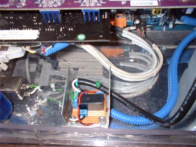

(Yes, I did cover the bare wires on the plug end, just not in this picture)



For the sake of safety, insulate the live connectors with a layer or two of heat-shrink tubing.
I’d rather keep 115 or 230V AC away from the insides of a water-cooled PC and build the relay board into the pump’s enclosure, or use a separate junction box. You may find it easier to use a 5VDC relay and power it from one of the USB ports.
There should be a diode across the relay’s coil (reverse-polarized, i.e. anode to GND and cathode to +5VDC or +12VDC). When a relay is turned off, a self-induction electromotive force (in other words, a voltage spike) appears at the coil and can lead to voltage surge and circuit damage. This diode shorts the spike.
All great points (and stated I did insulate the wires, just not in the pic) and sounds like you know a few things about electronics. This article was actually written way back in 2008 (even though it says 2012, that is when it was transferred from an old site) so at that time there were none of of the neat stuff for water cooling that is available now.