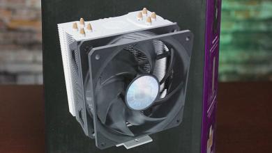
Scythe Ninja 4 CPU Cooler Review: All Hail the Kingslayer
Installation of the Scythe Ninja 4
UPDATE: December 2, 2015:
PSA: Users who are going to install the Scythe Ninja 4 on an Intel skylake CPU, please be aware of the latest Intel CPU’s thinner PCB substrate that can get damaged from exerting a lot of pressure. Scythe has issued the following statement about the matter (translated from German):
The company Scythe EU GmbH announces that on several coolers from its portfolio, a change of the mounting system for Skylake / plinth is made 1151st All coolers are in fact generally compatible with Skylake sockets, but it can in some cases result in damage to CPU and motherboard when the PC is exposed to stronger shocks (eg shipping or relocation). To prevent this, the pressure was reduced by an adjustment of the screw set. We will send the new set of screws you also like to charge. Please send your request via email to support@scythe.com or use the contact form on our website.
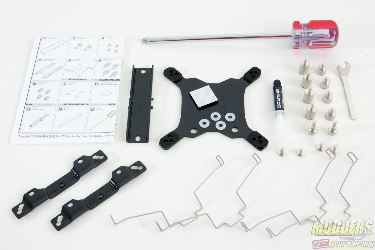
Everything required to install the Scythe Ninja 4 on an Intel system is provided in the bundle, including thermal interface material, screwdriver and a small hex spanner with angled tip. AMD users will require the use of the stock backplate bundled with their AMD motherboard instead of the provided backplate. All steps are the same otherwise.
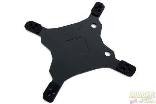
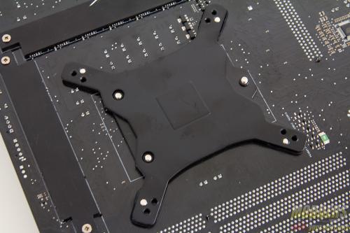
For Intel systems, the backplate has three different positioned holes to accommodate LGA775, LGA1366 and LGA115x sockets. Because people have been asking, yes LGA115x covers every single socket including LGA1151, LGA1150 and LGA1156 because the mounting hole distance is exactly the same for all of those models.
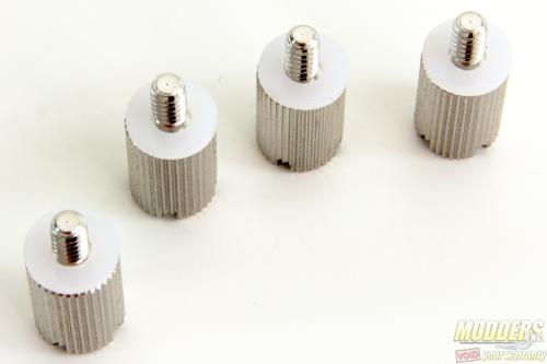
The main idea is to basically secure the backplate with the stud nuts with the white plastic spacers/washers as buffer so the metal stud nuts do not scratch the motherboard surface on the front. There are two kinds of stud nuts provided, one is shorter and one set is longer. The shorter one is for LGA2011 sockets with the integrated locking mechanism. For LGA775 sockets, the provided square padding must be added at the center of the backplate first.
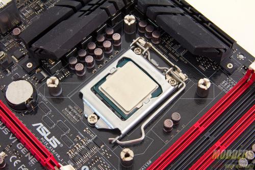
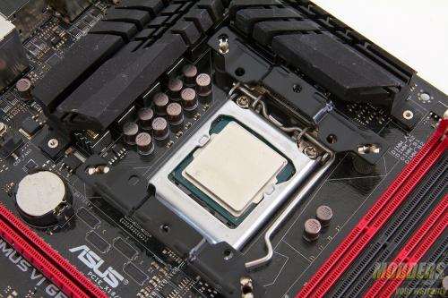
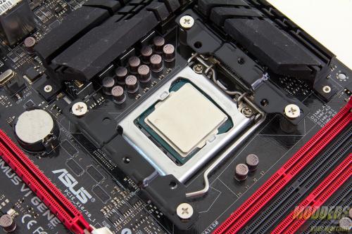
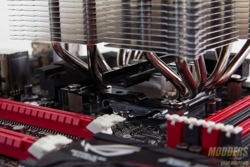
Position the backplate appropriately and take note of the position of the two holes at the top of the socket at the back of the motherboard. The tip edges of the backplate have padding that elevate the backplate and provide clearance for any surface mounted part close to the socket area. The stud nuts can be secured by hand or tightened by a screw driver. The pair of mounting plates install on top of these directly and secured with the four small flat screws provided. These mounting plates install with the curve facing inward and have three different mounting holes for LGA775, LGA115x and LGA1366 as well. Technically, the Scythe Ninja 4 can be installed on any orientation because of its equidistant measurement, but for optimal results, it must be installed with the fan blowing close across a group of heatpipes on one side so the mounting bars are installed at the top and bottom (pictured below):
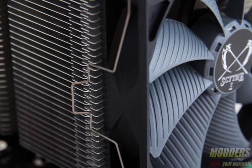
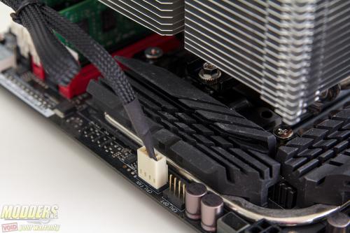
After the mounting bars are secured, apply thermal interface material on the CPU socket or on the heatsink contact surface (do not forget to remove the plastic cover first). To fully secure the Scythe Ninja 4, the mounting bar is slid in the middle and secured with the pair of large screws to the mounting plate. There is a cut-out on the aluminum fin stack that allows for the screwdriver provided to pass-through and secure these large screws in place. Afterwards, the mini-spanner can be used to tighten the contact further. Always make sure to tighten each incrementally so that pressure is distributed across properly. The last step is of course installing the fan and it is fairly self explanatory since the fan clips just attach to the edges.The measurement for these fan clips are remarkably exact and contact is very tight without being difficult to remove or install.
Do not forget to set the fan speed accordingly before installing the fan. For users with PWM motherboards, simply set the fan speed to maximum but for those who are going to plug the fan into a header with no PWM control, set the fan speed limiter accordingly.
Compatibility and Clearance Issues
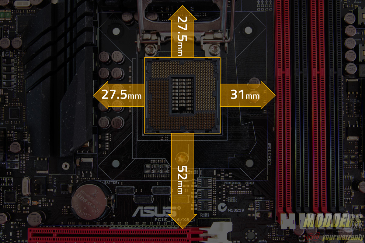
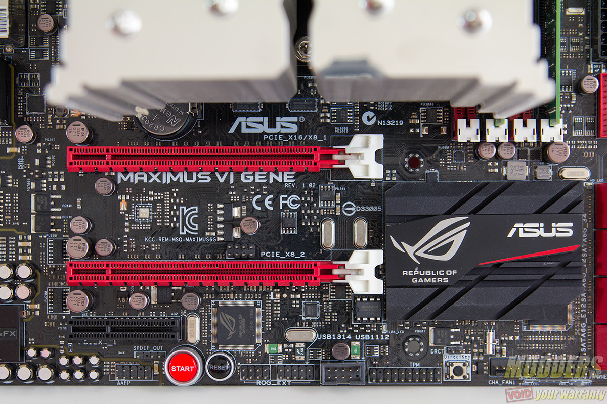
The test motherboard is an ASUS Maximus VI Gene micro-ATX motherboard and measuring from the edge of the socket (the gray plastic part), there is a 31mm gap between the CPU socket and the first DIMM slot as well as a 52mm clearance between the CPU socket and the topmost PCI-E x16 slot where the graphics card is installed:
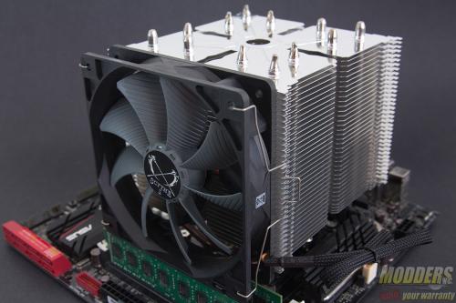
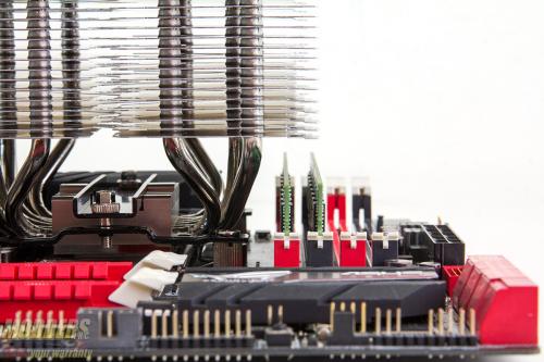
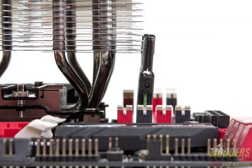
The DDR3 module used in the photo below measures 30mm tall in total (bare PCB). The Scythe Ninja 4 overhangs on top of the first and partially on the second DIMM slot although it provides a total clearance of 39.5mm from contact surface to the first aluminum fin for any module. For reference, the popular Corsair Vengeance DDR3 modules (1st gen.) are exactly 52.4mm tall at the most (measured at the tallest point) and although they can be installed on the 2nd DIMM slot, the aluminum fins are encroaching on it.
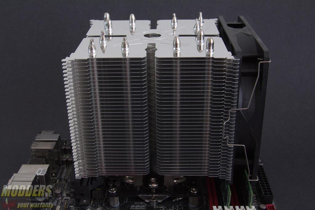
As with most heatsinks, the fan position can be adjusted to compensate for DRAM height clearance. An additional fan can also be installed on the opposite side as well but this extends the total length covered to 180mm across (130mm plus 2 x 25mm thick fans).
There are plenty of space for graphics cards on the PCI-E x16 slot however if there is no fan installed on the bottom facing side.
