Gigabyte Z170X-Gaming 7 Review: Everything and Then Some
A Closer Look at the Gigabyte Z170X-Gaming 7 Motherboard
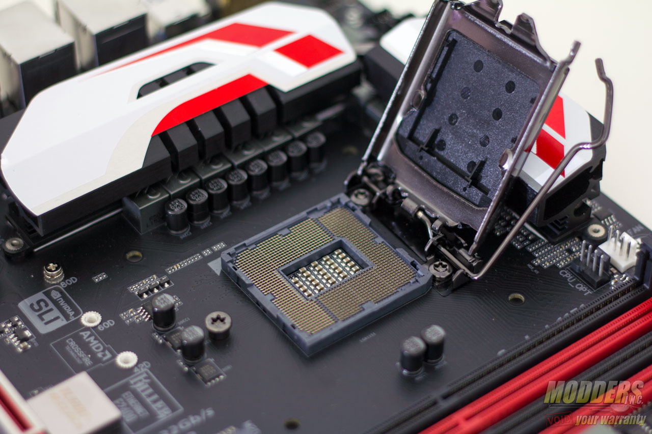
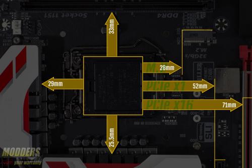
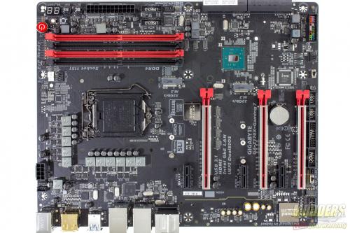
Z170 motherboards support LGA1151 CPUs but the heatsink compatibility remains the same as with LGA1150 and LGA1156 so previous generation heatsinks can be used. Despite the crowded PCB, there is decent clearance around the CPU socket and even the first PCI-E x16 slot for the graphics card is 71mm away so even large CPU coolers such as the NH-D15 will not pose a graphics card clearance issue.
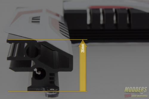
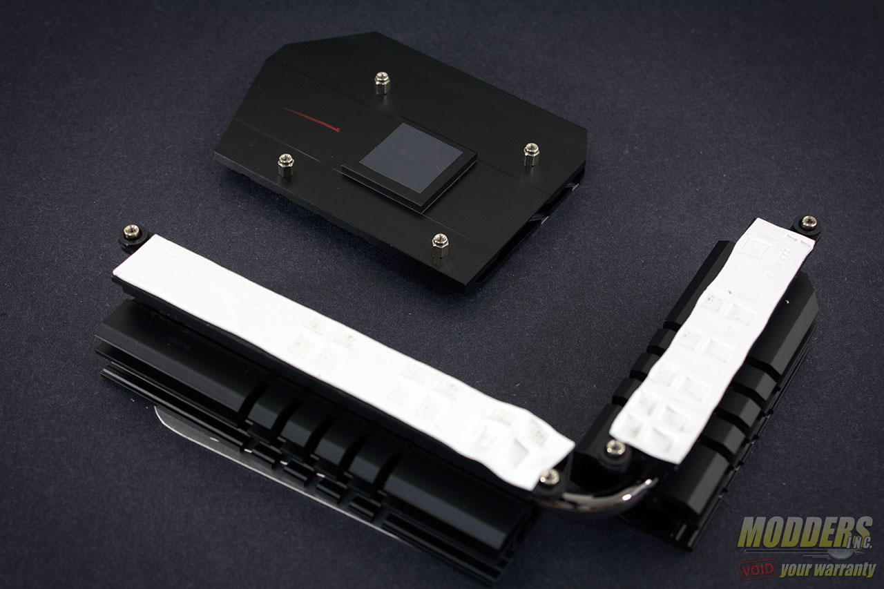
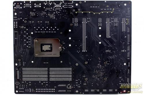
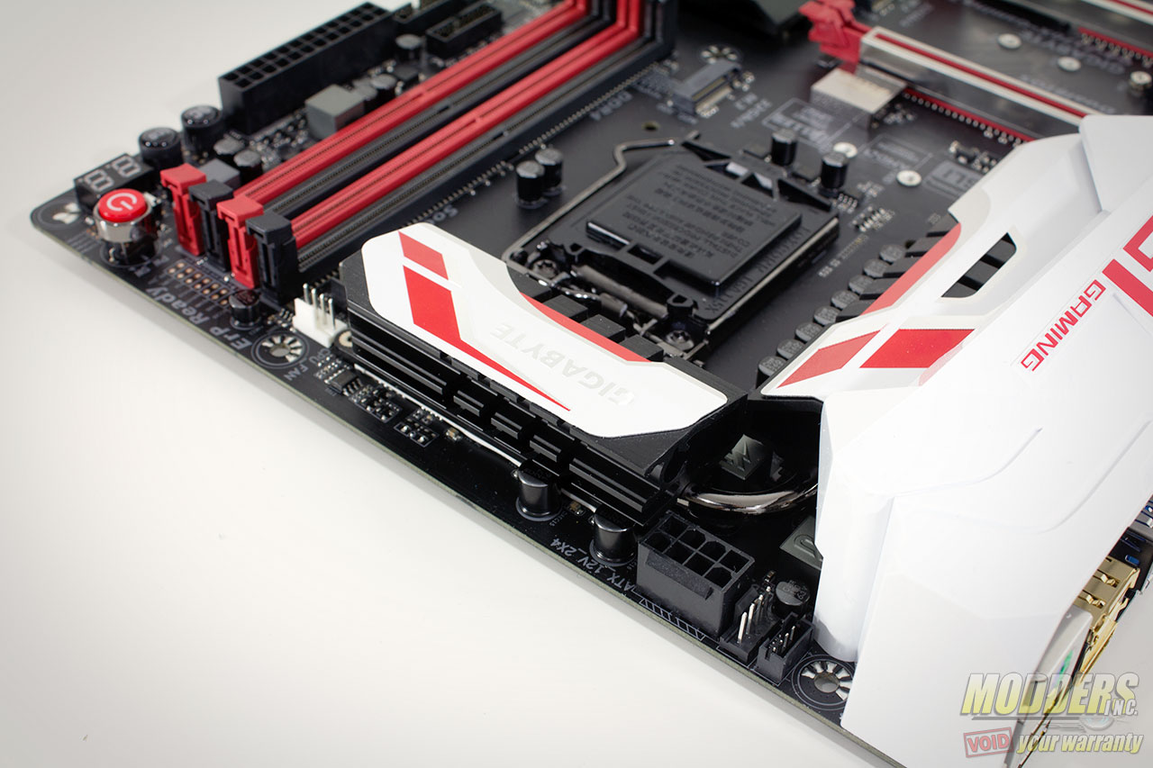
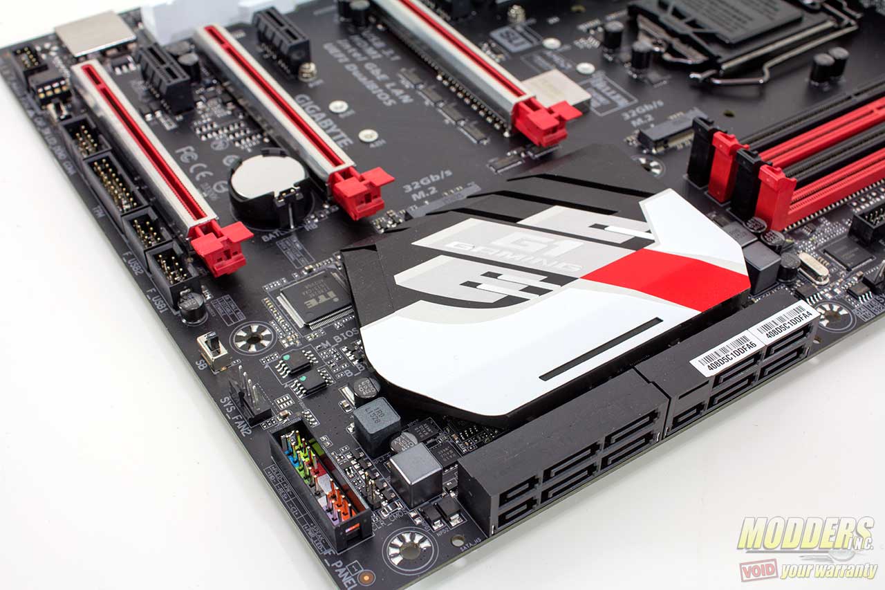
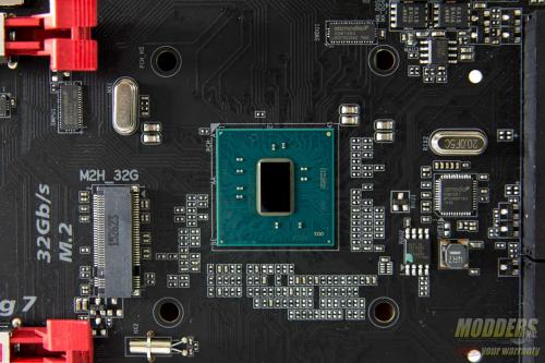
The VRM and chipset heatsinks are held in place by screws at the back and are solid pieces of black aluminum. There is a heatpipe joining the two pieces of VRM cooling. The white and red design at the top are glued in place so these would have to be removed first if users want to repaint the heatsinks. The chipset contact surface uses a thin graphite thermal tape since it has a very low TDP anyway but the VRM has a thicker thermal pad for the CPU, IGP and System Agent MOSFETs.
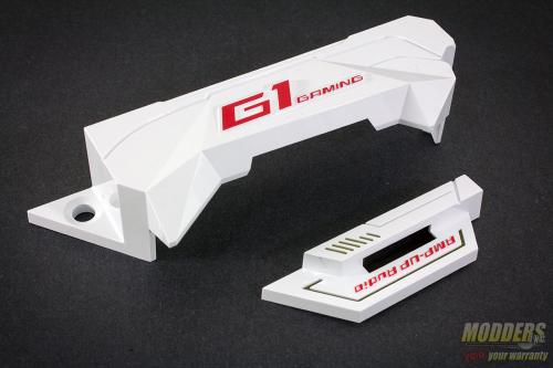
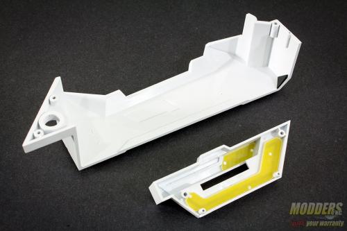
The IO cover and “Amp-up Audio” covers can be removed as well. These are white plastic and held in place at the rear by screws. The amp up audio has a bit of see-through plastic so users who want to repaint and mod this piece would have to push these out first so as not to obscure the LED effect.
With the covers removed, we can appreciate the Gigabyte Z170X-Gaming 7 further for its “personality” and see what really makes it special. Most of the covers are readily removable with the exception of the SoundCore 3Di cover and the Turbo BCLK cover which are soldered in place.
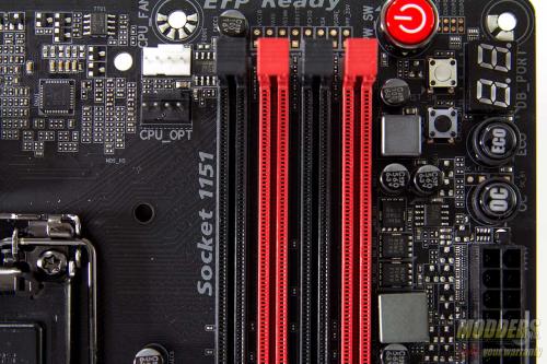
The 8-pin EPS12V CPU power connector is at the top right corner, tightly squeezed right above and beside the VRM heatsink and one fan header. Gigabyte was wise to make the latch for this power connector facing upward so it is easier to release later during uninstallation. This fan header is unusual but is a good location for the exhaust fan found on most mid-tower cases. I am surprised not more motherboard manufacturers place one in this location. Right beside this fan header is a power cable to power and control the rear-panel IO cover LED. To keep it neat, users are advised to route it underneath the top cover IO so minimal wires are exposed.
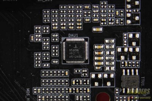
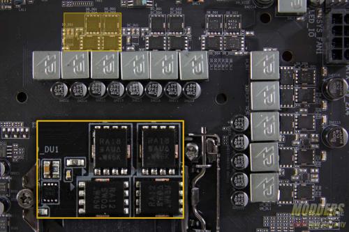
The main PWM controller is an Intersil ISL95856, a dual-output 4+3 phase capable IMVP8 controller from Intersil for the CPU+GT. ISL6625A are used as well as built-in drivers to drive Vishay SiRA18DP and SiRA12DP TrenchFETs per phase. Output filter has 500nH inductors with 560uF solid capacitors. The Turbo BCLK chip is hidden underneath the soldered cover. This is a secondary clock for BCLK adjustments.
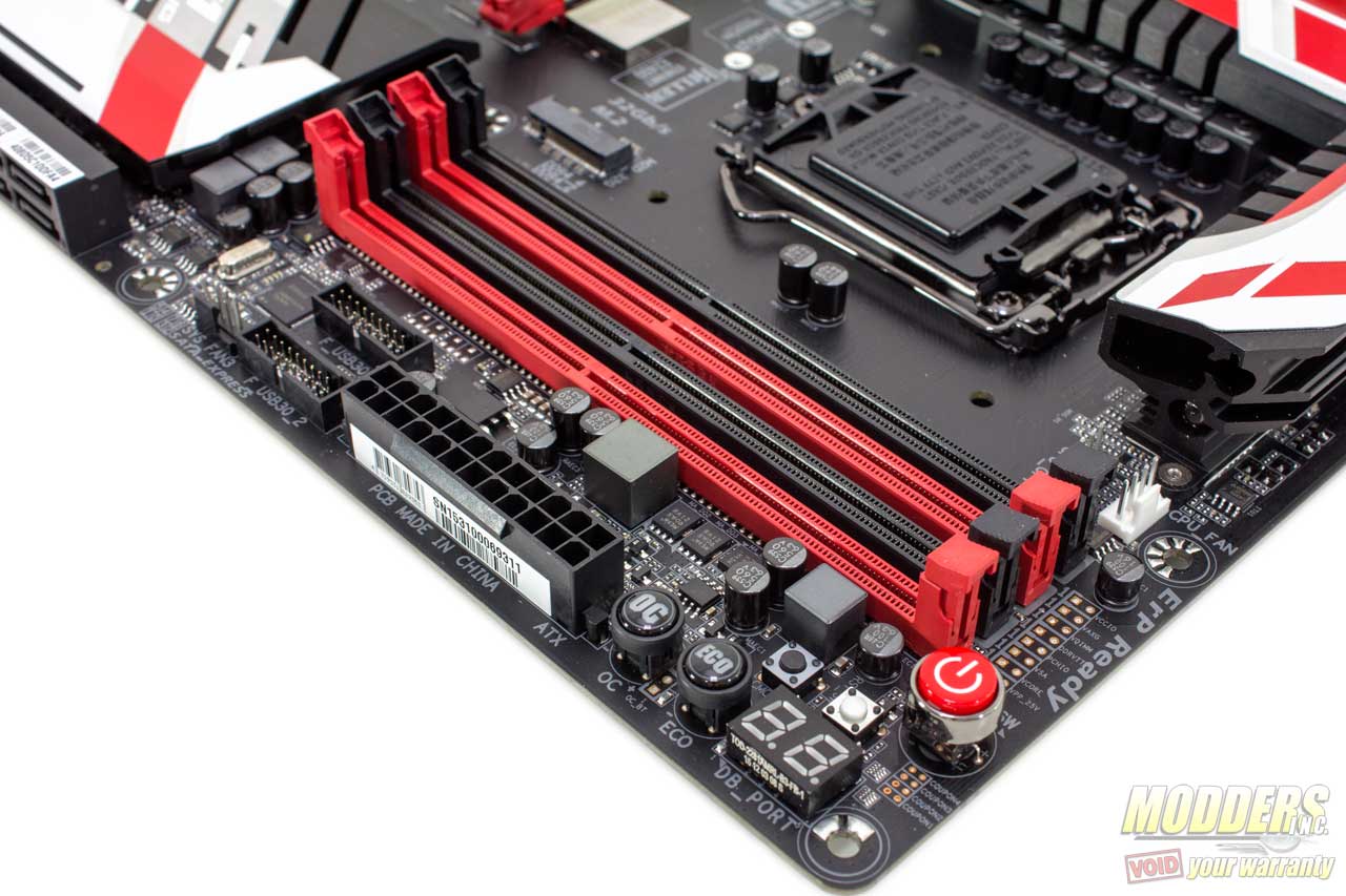
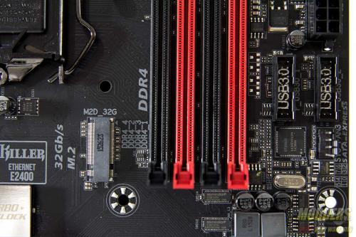
Memory VRM is handled by a Richtek RT8120D with three Vishay SiRA12DP TrenchFETs. Maximum memory capacity is 64GB with up to 4133MHz setting possible as of F5A BIOS update. At the top corner of the DIMM slots are voltage read-out points where users can point their multi-meter and measure voltages. On the top right corner are the on-board buttons and port 80 debug LED. The buttons include the power and reset buttons, as well as clear CMOS and single button shortcuts for OC and ECO mode.
Right below the 24-pin power are two 19-pin USB headers for dual USB 3.0 front panel output handled by a Renesas D720210 USB hub taking one USB 3.0 upstream from the chipset and providing four USB 3.0 downstream ports. More storage options continue right beside the large chipset heatsink in the form of two M.2 slots on the left side and eight SATA ports on the right side. These SATA ports are angled and three pairs can be used as SATA Express (Switched by an ASMedia 1480 per SATA pair). The two SATA ports at the top are provided by an ASMedia ASM1061 which takes one available PCI-E x1 from the chipset. All SATA ports support RAID except for these ASM1061 SATA ports.
M.2 slot possible configuration (AHCI and RAID):
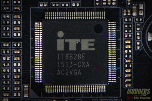
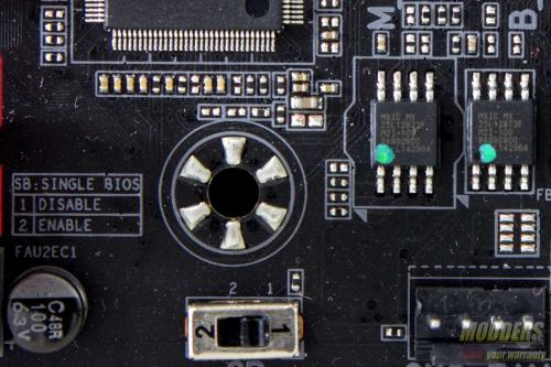
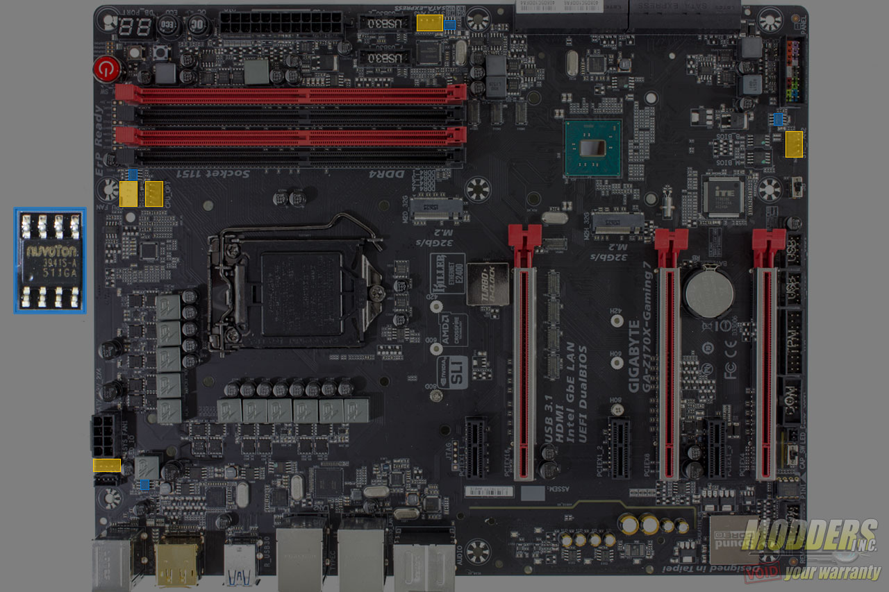
Along the bottom right corner is the front panel header but this should be very easy to spot considering it is color coded and the new accessory makes installation easy. With the Z170 chipset cover lifted the ITE8628E SuperIO is now visible as well as the pair of Macronix 128-Mbit flash chips for the BIOS storage. The ITE8628E SuperIO is in charge of hardware monitoring, PS/2 and Port 80 debug LED, aided by a Nuvoton 3941S for the remaining fan headers for individual PWM control. There are five PWM fan headers in total. Gigabyte includes a pair of ICs for the BIOS for redundancy and users can actually switch between running only a single BIOS chip or both for backup.
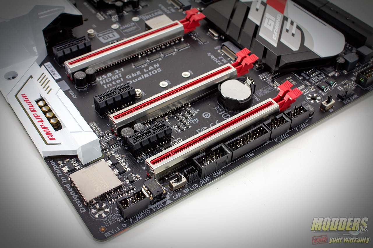
The remaining headers at the bottom edge include two 9-pin USB 2.0 headers, a Trusted Platform Module header, and a COM port header. Toward the edge in the audio subsection is a gain switch, a swappable OpAmp IC and the front panel audio header.
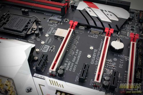
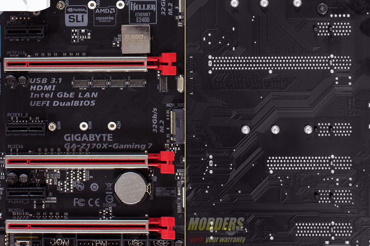
Expansion slot distribution is as follows (in order top to bottom):
- PCI-E 3.0 x1 via Z170
- PCI-E 3.0 x16 via CPU (x16, x8 when slot 4 is populated, switched by ASM1480)
- PCI-E 3.0 x1 via Z170
- PCI-E 3.0 x16 via CPU (x8)
- PCI-E 3.0 x1 via Z170
- PCI-E 3.0 x16 (x4 via Z170, shares bandwidth with second M.2 slot)
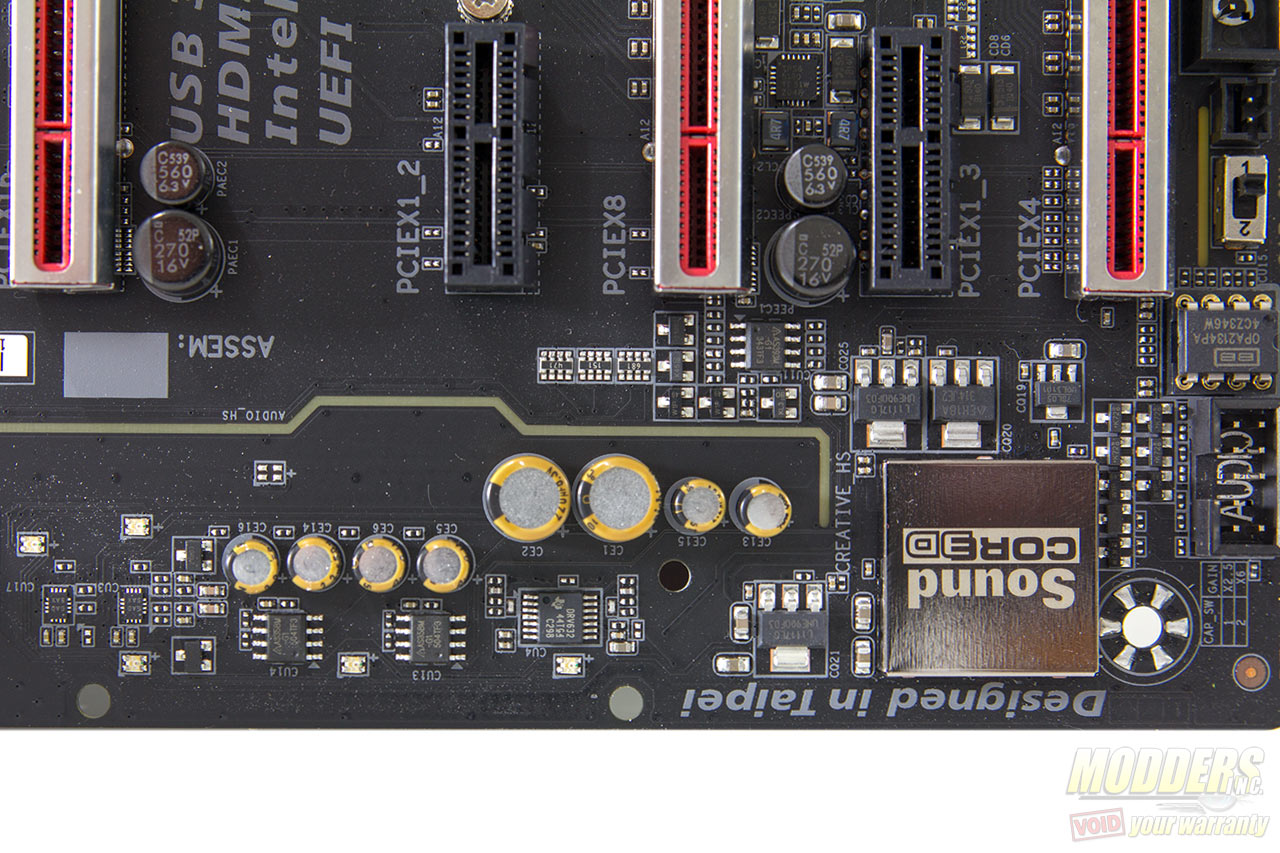
The audio subsystem is physically isolated from the rest of the PCB to minimize interference and audio is handled by a Creative SoundCore 3D quad-core processor, a superior solution to the common Realtek ALC1150 used in most current generation gaming motherboards. A Texas Instruments DRV632 line driver is used with a pair of ISL54405 multiplexers, Nichicon MW series capacitors and a swappable Burr-Brown OPA2134 OpAmp. This is not the first time Gigabyte has incorporated a swappable IC solution, first seen in their G1 Killer mainboard series and surprisingly nobody has copied them in this implementation yet. There is a gain switch for the rear output headphone users that drives the gain from the default 2.5x to 6x depending on the headphones used.
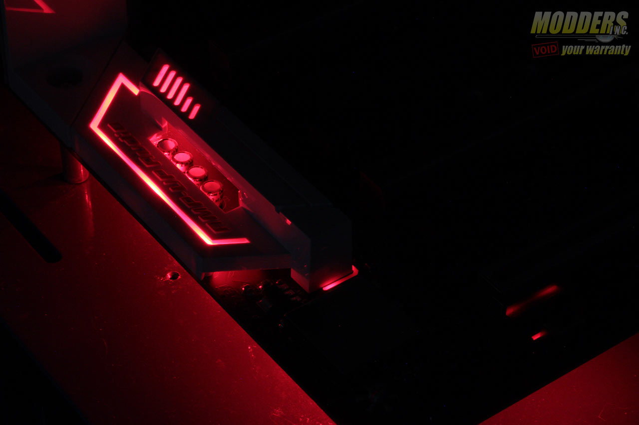
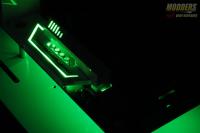
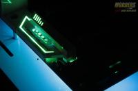
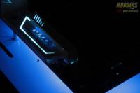
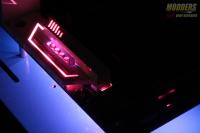
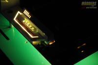
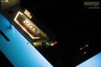
Behind the trace are a series of adjustable color LEDs that illuminate through the front, especially cool looking when the Amp-Up Audio cover is in place. This is adjustable via the UEFI or through the desktop via Gigabyte “Ambient LED” software. The rear IO also lights up similarly when plugged in. The default color is red to match the rest of the motherboard but just in case you modded it, you can adjust it to reflect six other colors. (Note that in the photos above and video below, the test bench is a light blue color as it is the DimasTech Mini V1 test bench previously reviewed here).
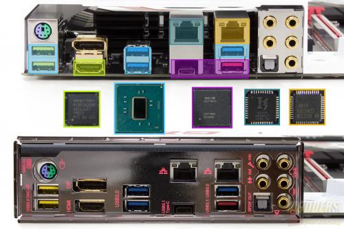
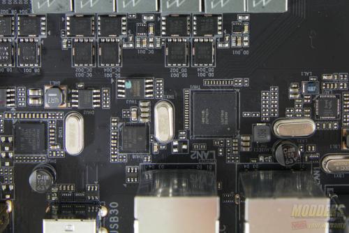
The rear PS2 port is provided by an ITE8628E Super IO chip which also handles system and temperature monitoring functions. There are two Gigabit Ethernet NICs included on the Gigabyte Z170X-Gaming 9, one is Intel’s latest “Jacksonville” i219V while the other is Killer’s E2400 Ethernet solution. Unfortunately teaming is not supported but they are each otherwise incredibly capable LAN solutions on their own. There is a DisplayPort (Maximum resolution supported is 4096×2160@24Hz or 3840×2160@60Hz) and HDMI port available for integrated graphics users. There are five gold-plated configurable analog audio jacks with one optical audio out. Five USB 3.0 ports are available and two of them (marked yellow) have Gigabyte’s USB DAC feature which means they have dedicated 5V power via independent DC-DC power supply pulled directly from the 8-pin CPU connector at the top, ideal for USB audio devices that require cleaner power. Two USB 3.1 ports are provided, one is Type-A and one is Type-C via Intel Thunderbolt USB 3.1 DSL6540 controller with a Texas Instrument TPS65982 Type-C and power delivery controller. This is the future of connectivity and it is nice to see that the Gigabyte Z170X-Gaming 7 is ready for it. It is pretty much essential at this point going forward even though there are not many devices yet that can fully saturate it yet.
